
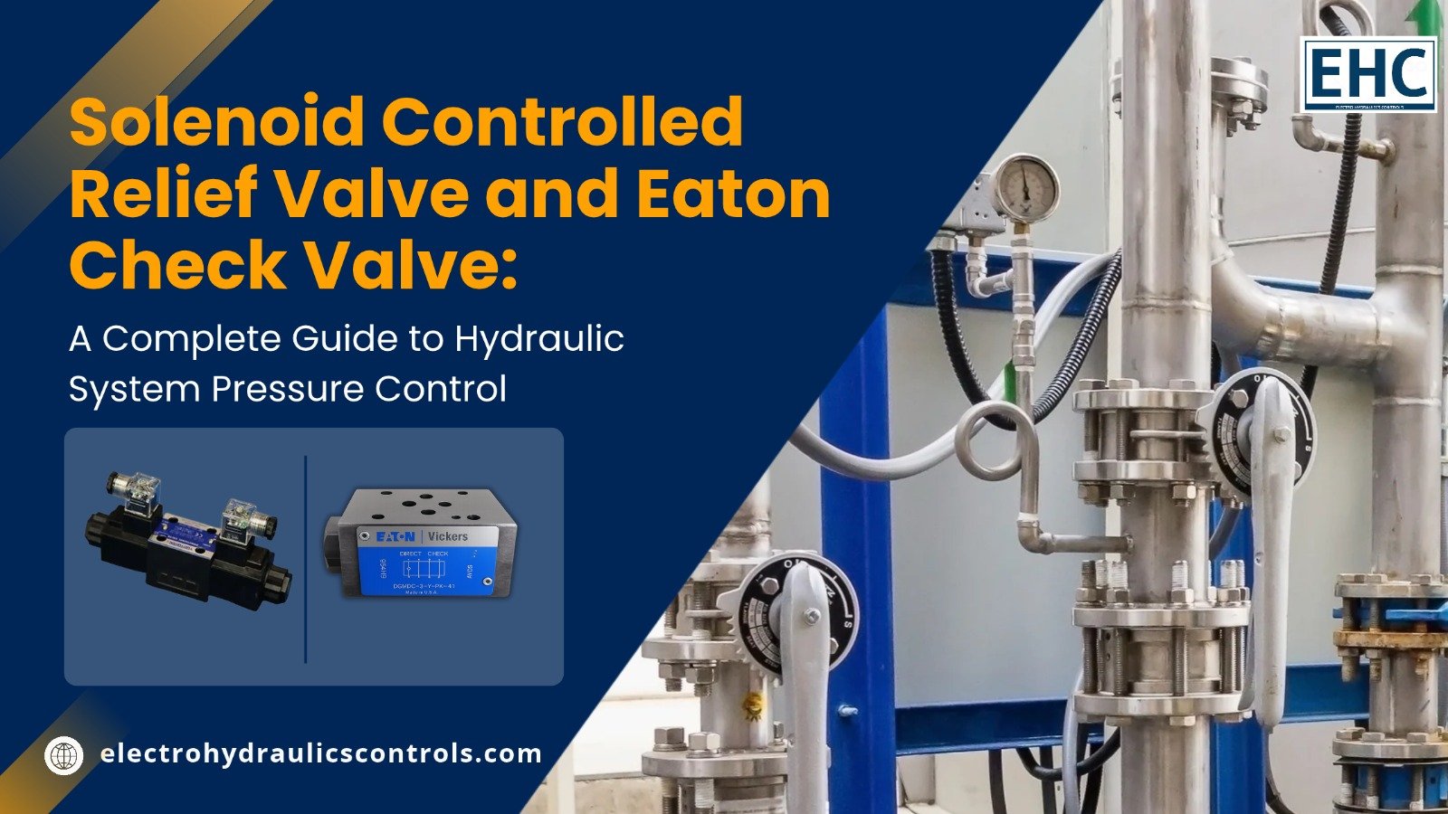
Solenoid Controlled Relief Valve and Eaton Check Valve: A Complete Guide to Hydraulic System Pressure Control
A hydraulic system requires accurate pressure regulation and reliable fluid-flow control to operate safely and efficiently. A solenoid controlled relief valve and an Eaton check valve are two important hydraulic components that help achieve these objectives.
A solenoid controlled relief valve regulates system pressure through an electrically operated solenoid mechanism, while an Eaton check valve allows hydraulic fluid to flow in one direction and prevents unwanted reverse flow. Together, these components help improve hydraulic system performance, protect equipment, and maintain operational reliability.
Understanding their functions, working principles, applications, and maintenance requirements can help industries select the right components for their hydraulic systems.
- Introduction to Hydraulic Pressure and Flow Control
Hydraulic systems are widely used in manufacturing plants, construction equipment, agricultural machinery, material-handling systems, and industrial automation. These systems use pressurised hydraulic fluid to transmit power and perform mechanical operations.
However, maintaining the correct pressure and controlling fluid direction are essential for smooth operation. Excessive pressure can damage pumps, pipelines, cylinders, and other hydraulic components. Similarly, unwanted reverse fluid flow can affect machine performance and reduce operational efficiency.
This is where pressure-control and flow-control components become important. Two such components are solenoid controlled relief valves and Eaton check valves, which perform different but complementary functions in hydraulic circuits.
For industrial hydraulic requirements and component information, explore solenoid controlled relief valve.
- What Is a Solenoid Controlled Relief Valve?
A solenoid controlled relief valve is a hydraulic pressure-control component that uses an electrically operated solenoid to control or modify the operation of a relief valve.
A conventional relief valve protects hydraulic systems by opening when system pressure reaches a predetermined setting. The excess hydraulic fluid is then directed back to the reservoir or another designated low-pressure line, preventing excessive pressure buildup.
In a solenoid-controlled design, electrical signals operate the solenoid mechanism, allowing pressure-control functions to be switched or adjusted according to the valve’s design.
How Does a Solenoid Controlled Relief Valve Work?
The working principle involves both electrical and hydraulic operations.
- Pressure development: The hydraulic pump supplies pressurised fluid to the hydraulic circuit.
- Pressure monitoring: System pressure acts on the relief valve’s internal mechanism.
- Electrical activation: An electrical signal energises the solenoid coil.
- Valve operation: The solenoid changes the position of the pilot or control mechanism, depending on the valve design.
- Pressure regulation: When the applicable pressure setting is reached, the valve opens and redirects excess fluid.
- System protection: The controlled pressure prevents excessive hydraulic loading and helps protect connected components.
The exact operation depends on whether the valve is direct-acting, pilot-operated, or an electrically controlled unloading arrangement.
Key Benefits of a Solenoid Controlled Relief Valve
- Effective Pressure Protection
It helps prevent excessive pressure from damaging hydraulic pumps, cylinders, hoses, and other circuit components.
- Electrical Control
The solenoid mechanism allows pressure-control functions to be integrated with electrical control panels, PLCs, and automated machinery.
- Improved Operational Efficiency
Appropriate pressure regulation helps hydraulic equipment operate within its intended working range.
- Flexible Machine Operation
Depending on the valve configuration, operators can activate different pressure-control or unloading functions through electrical signals.
- Equipment Protection
Maintaining pressure within specified limits can reduce unnecessary stress on hydraulic components and support longer equipment service life.
- What Is an Eaton Check Valve?
An Eaton check valve is a hydraulic component designed to allow fluid to flow in one direction while preventing reverse flow. It operates automatically through pressure differences and does not generally require an external electrical signal.
Eaton hydraulic check valves are available in different configurations, including inline, right-angle, manifold-mounted, and cartridge-style designs. The correct type depends on the hydraulic circuit, operating pressure, flow requirements, and installation arrangement.
How Does an Eaton Check Valve Work?
The operating principle is based on differential pressure.
- Forward fluid flow: Hydraulic fluid enters the inlet port and creates pressure against the internal poppet or ball.
- Opening movement: When inlet pressure exceeds the cracking pressure, the internal element moves away from its seat.
- Fluid passage: Hydraulic oil flows through the valve to the outlet port.
- Reverse pressure: When downstream pressure becomes greater than inlet pressure, the internal element moves back towards its seat.
- Flow prevention: The valve closes and prevents reverse hydraulic fluid movement.
The internal spring helps maintain the closed position when sufficient forward pressure is not available.
Important Benefits of an Eaton Check Valve
- Prevention of Reverse Flow
Its primary function is to prevent hydraulic oil from flowing backwards, helping maintain the intended direction of fluid movement.
- Protection of Hydraulic Components
Preventing reverse flow can help protect pumps and other circuit components from unwanted pressure or flow conditions.
- Improved System Reliability
Automatic operation reduces the need for manual intervention and supports consistent hydraulic performance.
- Reduced Internal Leakage
Certain poppet-type check valve designs use precision-machined sealing surfaces to minimise internal leakage.
- Multiple Installation Options
Different configurations allow engineers to select suitable valves for various industrial hydraulic circuit layouts.
- Difference Between a Solenoid Controlled Relief Valve and an Eaton Check Valve
Although both components are used in hydraulic systems, their functions are different.
| Feature | Solenoid Controlled Relief Valve | Eaton Check Valve |
| Primary function | Pressure control and unloading | Preventing reverse flow |
| Operation | Electrically controlled hydraulic mechanism | Automatic pressure-differential operation |
| Main purpose | Protects against excessive pressure | Maintains one-way fluid flow |
| Electrical requirement | Requires electrical control for solenoid operation | Generally does not require electricity |
| Typical application | Pressure regulation and unloading circuits | Pump outlets and flow-control circuits |
| Main advantage | Flexible pressure management | Reliable one-way flow protection |
Both components can be used in the same hydraulic circuit because they perform complementary functions.
- Applications in Industrial Hydraulic Systems
Solenoid controlled relief valves and Eaton check valves are useful across different industrial sectors.
Manufacturing and Production Equipment
Manufacturing machinery uses hydraulic systems for clamping, pressing, lifting, and positioning operations.
- Relief valves help maintain safe operating pressure.
- Check valves prevent unwanted reverse fluid movement.
- Both components contribute to consistent machine operation.
Construction Equipment
Excavators, loaders, lifting equipment, and other construction machines depend on reliable hydraulic power.
Pressure-control valves help protect hydraulic circuits, while check valves support controlled fluid movement.
Agricultural Machinery
Agricultural equipment such as tractors, harvesters, and hydraulic attachments requires dependable pressure and flow management.
These components can help maintain stable hydraulic operation during demanding field conditions.
Industrial Automation
Automated production lines require accurate hydraulic control and dependable component performance.
Solenoid-controlled pressure functions can be integrated with electrical control systems, while check valves maintain the required flow direction.
- Step-by-Step Guide to Selecting the Right Hydraulic Valve
Selecting the correct hydraulic component is essential for achieving reliable performance and avoiding unnecessary maintenance costs.
Follow these steps before purchasing or installing a valve.
Step 1: Identify the Application
Determine whether your system requires pressure regulation, unloading, reverse-flow prevention, or a combination of these functions.
Step 2: Check Operating Pressure
Review the maximum operating pressure of the hydraulic system. Select a valve with an appropriate pressure rating and adjustment range.
Step 3: Evaluate Flow Requirements
Check the hydraulic pump’s flow rate and ensure that the selected valve can handle the required fluid volume.
Step 4: Consider Electrical Specifications
For a solenoid controlled relief valve, verify the solenoid voltage, electrical connections, duty cycle, and control requirements.
Step 5: Check Cracking Pressure
For an Eaton check valve, consider the cracking pressure required to open the valve and the acceptable pressure drop during normal operation.
Step 6: Verify Hydraulic Compatibility
Check the hydraulic fluid type, operating temperature, port connections, mounting arrangement, and seal compatibility.
Step 7: Purchase from a Reliable Supplier
Choose genuine components with appropriate technical documentation and manufacturer specifications.
For additional hydraulic component information and sourcing requirements, visit Eaton check valve.
- Maintenance Tips for Better Hydraulic Valve Performance
Regular maintenance helps prevent unexpected equipment failures and supports long-term hydraulic system reliability.
Important maintenance practices include:
- Inspect hydraulic oil: Check oil cleanliness and replace contaminated fluid according to manufacturer recommendations.
- Monitor system pressure: Use suitable pressure gauges to identify abnormal pressure fluctuations.
- Check for leakage: Inspect valve bodies, connections, seals, and hydraulic lines.
- Inspect electrical connections: Ensure that solenoid wiring and connectors are secure and undamaged.
- Monitor valve performance: Look for delayed operation, unusual noise, overheating, or inconsistent pressure control.
- Follow manufacturer guidelines: Maintain the components according to their specified operating limits and service intervals.
Always depressurise the hydraulic system and follow appropriate safety procedures before inspecting or servicing its components.
- Scientific and Engineering Principles Behind Hydraulic Valves
The working principles of these components are based on established fluid mechanics and electromagnetic principles.
Pressure regulation: A relief valve operates when hydraulic pressure generates sufficient force to overcome the valve’s spring or pilot-control forces. This allows excess fluid to flow towards the tank or designated return line.
Electromagnetic actuation: A solenoid generates a magnetic field when electrical current passes through its coil. This magnetic force moves a plunger or control element, allowing the valve to change its operating state.
Differential pressure: A check valve responds to the pressure difference across its internal moving element. Forward pressure opens the valve when the required cracking pressure is reached, while reverse pressure helps close it.
These principles are explained in hydraulic engineering references and manufacturer documentation. Yuken describes solenoid controlled relief valves as combinations of pilot-operated relief valves and solenoid-operated directional valves, while Eaton’s Vickers documentation explains the one-way flow operation of check valves.
yuken.co.jp+2
- Frequently Asked Questions (FAQs)
Q1. What is the main purpose of a solenoid controlled relief valve?
Its main purpose is to regulate hydraulic pressure and provide electrically controlled pressure or unloading functions, depending on the valve design.
Q2. How does an Eaton check valve prevent reverse flow?
It uses an internal poppet or ball mechanism that opens under sufficient forward pressure and closes when reverse pressure acts on the valve.
Q3. Can a solenoid controlled relief valve and an Eaton check valve work together?
Yes. They can be installed in the same hydraulic circuit. The relief valve manages pressure, while the check valve controls the direction of fluid flow.
Q4. Are Eaton check valves suitable for industrial applications?
Yes. Eaton check valves are available in different configurations and pressure ratings for industrial hydraulic applications. Selection should be based on the specific model’s technical specifications.
Q5. What causes hydraulic check valve failure?
Common causes include contaminated hydraulic oil, damaged sealing surfaces, spring fatigue, incorrect installation, and operation outside the specified pressure or flow limits.
Q6. How often should hydraulic valves be inspected?
Inspection frequency depends on operating conditions, equipment usage, and manufacturer recommendations. Systems operating under heavy loads or in contaminated environments may require more frequent inspections.
Q7. Why is pressure regulation important in hydraulic systems?
Pressure regulation helps prevent excessive hydraulic loading, protects system components, and keeps equipment operating within its designed pressure range.
- Conclusion
Solenoid controlled relief valves and Eaton check valves play important roles in maintaining hydraulic system safety, efficiency, and reliability. While solenoid controlled relief valves provide electrically controlled pressure regulation and unloading functions, Eaton check valves prevent unwanted reverse fluid movement.
Understanding their operating principles, technical specifications, and applications helps engineers and maintenance professionals make better component-selection decisions.
Choosing suitable hydraulic valves, maintaining clean hydraulic fluid, and following manufacturer guidelines can improve equipment reliability and reduce unexpected downtime. For industrial hydraulic applications, selecting quality components that match the system’s operating requirements is essential for achieving consistent performance.
Author Bio
About the Author
The Electro Hydraulics Controls Editorial Team creates informative content covering hydraulic systems, industrial automation, fluid power technology, and hydraulic components. The team focuses on explaining technical concepts, component applications, and maintenance practices to help engineers, technicians, and industrial professionals make informed decisions.
Add comment