
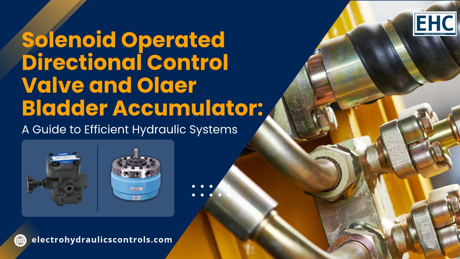
Solenoid Operated Directional Control Valve and Olaer Bladder Accumulator: A Guide to Efficient Hydraulic Systems
A solenoid operated directional control valve and an Olaer bladder accumulator are two important components used to improve the control, efficiency, and reliability of hydraulic systems. The directional control valve regulates the direction of hydraulic fluid using an electrically operated solenoid, while the bladder accumulator stores hydraulic energy under pressure and releases it when required. When properly selected and integrated, these components help industrial machinery achieve smooth operation, consistent pressure, and improved energy management.
What Is a Solenoid Operated Directional Control Valve?
A solenoid operated directional control valve is an electrohydraulic component that controls the direction of hydraulic fluid flow in a hydraulic circuit. It uses an electromagnetic solenoid to move an internal spool or another switching mechanism, directing pressurized oil toward the required actuator.
These valves are widely used in manufacturing equipment, hydraulic presses, injection moulding machines, material handling systems, and industrial automation applications.
How Does It Work?
The working principle is based on electromagnetic force. When an electrical signal energizes the solenoid coil, the resulting magnetic field moves the valve mechanism into a selected position. This changes the internal flow passages and directs hydraulic fluid to the appropriate port.
When the electrical signal is removed, a spring or another return mechanism may move the valve back to its original position, depending on the valve design.
Key Benefits
- Precise directional control: Directs hydraulic fluid to cylinders or hydraulic motors as required.
- Electrical automation: Supports integration with PLCs, sensors, and automated control systems.
- Faster operation: Enables electrically commanded switching without manual valve operation.
- Compact design: Fits many industrial hydraulic power units and machinery layouts.
- Improved repeatability: Provides consistent switching when the valve is correctly sized and operated within its specified limits.
Selecting the right valve requires consideration of operating pressure, flow rate, voltage, number of ports and positions, spool configuration, response time, and fluid compatibility.
What Is an Olaer Bladder Accumulator?
An Olaer bladder accumulator is a hydraulic energy-storage device that uses compressed gas, typically nitrogen, separated from hydraulic fluid by a flexible bladder. Olaer is a name associated with hydraulic accumulator technology, including products used in industrial hydraulic systems.
The accumulator stores energy by compressing the gas as hydraulic fluid enters its shell. When system pressure decreases or additional fluid is needed, the expanding gas pushes the stored fluid back into the hydraulic circuit.
How Does a Bladder Accumulator Work?
A typical bladder accumulator contains a pressure-resistant shell, a flexible bladder, a gas charging valve, and a hydraulic fluid connection.
Its operating process follows these steps:
- Nitrogen is introduced into the bladder at the specified pre-charge pressure.
- Hydraulic fluid enters the accumulator when system pressure exceeds the gas pressure.
- The incoming fluid compresses the nitrogen, storing hydraulic energy.
- When system pressure falls or demand increases, the compressed gas expands and pushes fluid back into the circuit.
- The accumulator helps maintain the required pressure and supplies additional fluid within its design limits.
Bladder accumulators must be correctly sized and pre-charged for the intended application. The appropriate gas pre-charge depends on operating pressures, temperature, fluid demand, and the manufacturer’s specifications.
Key Benefits of an Olaer Bladder Accumulator
- Energy storage: Stores pressurized hydraulic fluid for later use.
- Pressure stabilization: Helps reduce pressure fluctuations caused by changing operating conditions.
- Shock absorption: Can reduce hydraulic pressure surges when properly selected and installed.
- Emergency fluid supply: Provides a limited reserve of pressurized fluid for suitable backup functions.
- Pump demand management: Can reduce frequent pump cycling in appropriately designed hydraulic systems.
- Pulsation damping: Helps minimize pressure pulsations in compatible hydraulic circuits.
The accumulator’s capacity, maximum working pressure, fluid compatibility, temperature range, and pre-charge requirements should always be checked before installation.
Why Are These Two Components Important Together?
A solenoid operated directional control valve and an Olaer bladder accumulator perform different but complementary functions. The valve controls where hydraulic fluid flows, while the accumulator stores energy and helps manage pressure variations.
When incorporated into a properly engineered hydraulic circuit, they can support reliable and responsive machine operation.
For example, in an automated hydraulic press, the directional control valve can direct fluid to extend or retract a cylinder. An appropriately sized bladder accumulator can supply additional fluid during peak demand or help absorb pressure fluctuations, depending on the circuit design.
The accumulator does not replace the pump or directional control valve. Instead, it works alongside them to meet specific system requirements.
Comparison of Their Functions
| Feature | Solenoid Operated Directional Control Valve | Olaer Bladder Accumulator |
| Primary function | Controls fluid direction | Stores hydraulic energy |
| Operating principle | Electromagnetic actuation | Gas compression and expansion |
| Main components | Solenoid coil and valve mechanism | Pressure shell and flexible bladder |
| Typical benefit | Automated flow switching | Pressure support and energy storage |
| Common applications | Hydraulic cylinders and motors | Shock absorption and peak-flow support |
| Maintenance focus | Coil, seals, spool movement, and contamination | Gas pre-charge, bladder condition, and leakage |
Applications in Industrial Hydraulic Systems
Both components are used across industries where controlled hydraulic power and dependable performance are essential.
- Manufacturing and Automation
Directional control valves allow automated machinery to move cylinders and actuators according to programmed sequences. Accumulators can support short-duration flow demand and help stabilize pressure.
- Hydraulic Presses
A solenoid operated directional control valve can control cylinder movement during pressing and return operations. An accumulator may provide supplementary flow during high-demand stages when the hydraulic circuit is designed for that purpose.
- Mobile and Material Handling Equipment
Hydraulic systems used in lifting and material handling can benefit from electrically controlled fluid direction and accumulator-based energy storage. Actual suitability depends on pressure, load, and safety requirements.
- Industrial Power Units
Hydraulic power units may use directional control valves to operate multiple functions and bladder accumulators to manage pulsations, pressure fluctuations, or intermittent fluid demand.
- Heavy Industrial Machinery
In suitable applications, these components contribute to more controlled operation, reduced pressure disturbances, and improved hydraulic system responsiveness.
Step-by-Step Guide to Selecting the Right Components
Choosing compatible components is essential for achieving reliable hydraulic performance.
Step 1: Identify the System Requirements
Determine the machine’s operating pressure, required flow rate, actuator type, duty cycle, and operating environment. These parameters establish the basic selection criteria.
Step 2: Select the Directional Control Valve
Check the valve’s rated pressure and flow capacity, port configuration, number of switching positions, solenoid voltage, spool type, and return mechanism. Confirm that its flow characteristics meet the actuator’s requirements.
Step 3: Calculate the Accumulator Requirements
Determine the required fluid volume, minimum and maximum operating pressures, expected pressure changes, and available response time. Accumulator sizing should be based on the intended function rather than shell capacity alone.
Step 4: Verify Compatibility
Check the hydraulic fluid, seal materials, operating temperature, connection sizes, mounting arrangement, and pressure ratings of both components. Confirm that the accumulator is suitable for the specific hydraulic circuit.
Step 5: Plan Safe Installation
Install the directional control valve according to the hydraulic schematic and the manufacturer’s instructions. Mount and connect the accumulator using approved fittings and appropriate pressure-rated components.
Step 6: Test System Performance
Check for external leakage, abnormal noise, pressure instability, valve response issues, and unexpected actuator movement. Verify that the system operates within its specified pressure and temperature limits.
Step 7: Follow a Preventive Maintenance Schedule
Inspect valve coils, electrical connections, seals, and fluid cleanliness. For bladder accumulators, follow the manufacturer’s procedure for checking nitrogen pre-charge and inspecting the unit for damage or leakage.
Safety note: Hydraulic accumulators retain stored energy even after a pump has stopped. Before servicing, isolate the equipment, release hydraulic pressure using the approved procedure, and verify that the accumulator is safely depressurized on the hydraulic side. Never use oxygen or compressed air to charge a nitrogen accumulator.
Best Practices for Improving Hydraulic System Performance
To maintain reliable operation, consider the following practices:
- Use clean hydraulic fluid and suitable filtration.
- Avoid operating valves beyond their rated pressure and flow limits.
- Select the correct accumulator pre-charge for the intended application.
- Monitor fluid temperature and pressure during operation.
- Inspect hydraulic hoses, fittings, and seals regularly.
- Follow the manufacturer’s installation and maintenance documentation.
- Ensure that pressure-relief and other required safety devices are correctly designed and installed.
A well-maintained hydraulic system can reduce unplanned downtime, protect equipment, and provide more predictable machine performance.
Frequently Asked Questions (FAQs)
- What is the main function of a solenoid operated directional control valve?
Its main function is to control the direction of hydraulic fluid flow using an electrical signal. It helps operate hydraulic cylinders and motors in automated machinery.
- What does an Olaer bladder accumulator do?
An Olaer bladder accumulator stores hydraulic energy using compressed nitrogen separated from the hydraulic fluid by a flexible bladder. It can supply stored fluid, stabilize pressure, and absorb hydraulic shocks when appropriately selected.
- Can a bladder accumulator increase hydraulic system pressure?
An accumulator can support pressure during certain demand conditions, but it does not continuously generate pressure like a pump. Its ability to supply fluid depends on its pre-charge, stored fluid volume, and the system’s operating pressures.
- Can these components be used in the same hydraulic circuit?
Yes. A directional control valve and a bladder accumulator can operate in the same circuit when the system is properly engineered. Their compatibility depends on the circuit layout, pressure ratings, flow requirements, and safety provisions.
- How often should a bladder accumulator be inspected?
Inspection frequency depends on the operating conditions, applicable regulations, and the manufacturer’s recommendations. Regular checks should include external condition, leakage, mounting, and nitrogen pre-charge where required.
- What causes a solenoid operated directional control valve to malfunction?
Common causes include electrical supply problems, damaged solenoid coils, contaminated hydraulic fluid, spool sticking, seal wear, and operation outside the valve’s specified limits.
- How do I choose the correct accumulator size?
Accumulator sizing depends on the required usable fluid volume, minimum and maximum working pressures, pre-charge pressure, temperature, and intended function. Engineering calculations and manufacturer sizing guidance should be used.
Conclusion
A solenoid operated directional control valve and an Olaer bladder accumulator are valuable components in modern hydraulic engineering. The directional control valve provides electrical control over fluid movement, while the bladder accumulator stores hydraulic energy and helps manage pressure variations.
Understanding their operating principles, selecting suitable specifications, and following correct installation and maintenance procedures can improve hydraulic system reliability, efficiency, and operational safety. For industrial applications, component selection should always be based on actual system requirements and verified manufacturer documentation.
Author Bio
Author: Industrial Hydraulics Content Team
The Industrial Hydraulics Content Team develops educational content on hydraulic systems, fluid-power components, industrial automation, and equipment maintenance. The team’s goal is to help engineers, maintenance professionals, and industrial buyers understand component functions and make informed equipment-selection decisions. Technical recommendations should be verified against the relevant manufacturer’s specifications and application requirements.



Add comment