
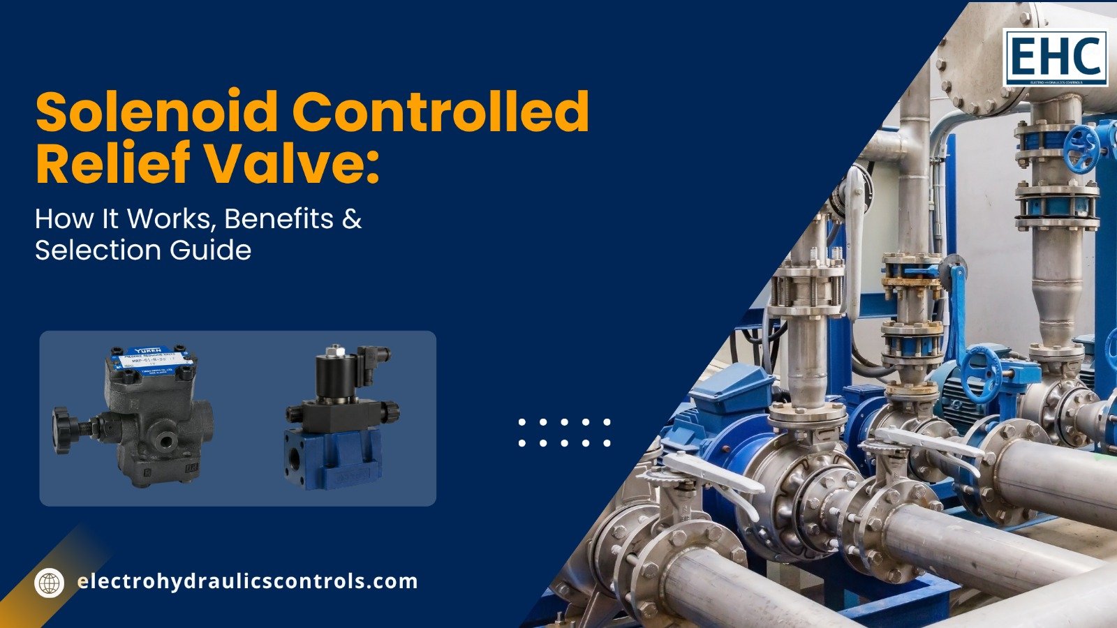
Solenoid Controlled Relief Valve: How It Works, Benefits & Selection Guide
A solenoid controlled relief valve (also called a solenoid operated relief valve) combines a pilot-operated relief valve with a solenoid-operated directional valve. This integration lets you unload pump pressure remotely with an electrical signal or switch between pressure settings without extra piping. It protects hydraulic systems from overpressure while enabling energy-saving unloading and multi-pressure control in industrial circuits.
What Is a Solenoid Controlled Relief Valve?
A solenoid controlled relief valve is a hydraulic pressure-control component that merges a conventional pilot-operated relief valve with a solenoid directional valve mounted directly on the relief body and connected to the vent port.
When the system pressure reaches the preset limit, the valve opens and routes excess fluid to tank, limiting maximum pressure. The solenoid allows remote electrical control: energizing or de-energizing it can vent the pilot stage (unloading the pump at low pressure), restore the relief setting, or select between different pressure levels when remote pilot relief valves are connected to the solenoid ports.
This design eliminates separate piping between the relief and directional valves, reduces potential leak points, and supports both fixed-displacement pump unloading and multi-stage pressure circuits.
Why Solenoid Controlled Relief Valves Matter
These valves deliver practical advantages that improve safety, efficiency, and system design:
- Remote electrical unloading of fixed-displacement pumps, cutting heat generation and energy waste during idle periods.
- Compact integration that removes external tubing and simplifies manifold layouts.
- Ability to select one, two, or three pressure levels (plus vent) using single or double solenoids.
- Faster response for start/stop of motors or deceleration of actuators compared with purely mechanical alternatives.
- Compatibility with automated control systems, pressure switches, and PLCs.
- Protection of pumps, actuators, and lines from pressure spikes caused by load changes or blocked flow paths.
In applications such as hydraulic presses, machine tools, injection molding, material handling, and industrial power packs, the combination of reliable pressure limiting and electrical control makes system operation safer and more efficient.
How a Solenoid Controlled Relief Valve Works
The valve uses a two-stage design. The main stage is a balanced piston or poppet relief that senses system pressure at the inlet. A small pilot flow through an orifice controls the main stage.
Under normal conditions the pilot stage holds the main stage closed until inlet pressure reaches the spring-adjusted setting. At that point the pilot opens, unbalancing the main stage so it lifts and dumps flow to tank.
The solenoid directional valve sits on the vent port. When the solenoid vents the pilot chamber to tank, the main stage opens at very low pressure and the pump unloads. When the solenoid blocks the vent, the relief function returns to its set pressure. Different spool configurations (normally open/vented, normally closed/relief, dual-pressure, or three-pressure) determine the exact sequence of operations when the solenoid is energized or de-energized.
Back pressure on the tank port adds directly to the relief setting (1:1 ratio), so tank-line design must be considered. Many designs include a vent restrictor option to soften the transition from loaded to unloaded pressure and reduce shock.
Common Configurations and Options
Manufacturers such as Yuken (BSG/BST series) and Sun Hydraulics (FLeX RVC series) offer several practical variants:
- Single-solenoid normally vented (energize to relieve) or normally relieving (energize to vent).
- Double-solenoid versions for dual or triple pressure selection plus vent.
- Sub-plate or threaded mounting.
- Flow ratings typically from 100 L/min to 400 L/min depending on size (03, 06, 10).
- Maximum pressures commonly 210–350 bar.
- Coil voltages in AC or DC, with various connector styles and IP ratings.
- Optional high-venting or vent-restrictor versions for faster or smoother response.
Cartridge-style solenoid-operated relief valves provide similar functions in a more compact cavity for manifold systems.
Step-by-Step Guide to Selecting and Applying a Solenoid Controlled Relief Valve
- Define the maximum system pressure and required relief setting. Choose a valve whose adjustable range covers the working pressure with adequate margin.
- Calculate peak flow that must be relieved. Size the valve so the pressure rise at full flow stays within acceptable limits.
- Decide the control logic: simple unload/load, dual pressure, or three-pressure selection. Match the solenoid spool type (2B3A, 2B3B, 3C2, etc.) to the circuit needs.
- Confirm electrical requirements (voltage, connector type, duty cycle) and environmental conditions (temperature, contamination, hazardous location if applicable).
- Select mounting style (sub-plate, threaded, or cartridge) that fits the manifold or power-pack layout.
- Check tank-line pressure effects and, if needed, specify a model with a vent restrictor for shock reduction.
- Install with clean fluid, proper filtration, and correct torque on mounting bolts. Set the pressure with the system at operating temperature and verify response with the solenoid.
- Integrate the solenoid signal with the machine control so unloading occurs during idle and relief is restored only when work is required.
Practical Application Tips
Use a normally open (vented) solenoid controlled relief valve with fixed-displacement pumps so the pump unloads whenever the machine is not performing work. Energize the solenoid only when actuators need pressure.
In hi-lo pump circuits the valve can unload the high-volume pump once system pressure reaches the low-pressure threshold.
For deceleration of free-falling loads or soft start of large motors, a normally closed version can be switched by a limit switch or timer to create a controlled pressure ramp.
Always keep the tank line short and generously sized; excessive back pressure raises the effective relief setting and can cause instability.
Frequently Asked Questions
What is the difference between a solenoid controlled relief valve and a standard relief valve?
A standard relief valve is purely mechanical and continuously set. A solenoid controlled version adds electrical remote unloading or multi-pressure selection without extra piping.
Can I use a solenoid operated relief valve to unload a fixed-displacement pump?
Yes. This is one of the most common applications. When the solenoid vents the pilot stage, pump flow returns to tank at low pressure, reducing heat and power consumption.
Do these valves require special fluid cleanliness?
They perform best with clean fluid. Contamination can affect the pilot orifice and solenoid spool. Maintain proper filtration as recommended by the manufacturer.
How quickly does the valve respond when the solenoid is energized?
Response is typically measured in tens of milliseconds. A slight delay is normal and usually only noticeable on very fast cycles. Vent-restrictor models deliberately slow the transition to reduce shock.
Are solenoid controlled relief valves interchangeable between brands?
Mounting interfaces and cavity sizes vary. Always verify port pattern, cavity, and performance data before substitution.
Conclusion
A well-chosen solenoid operated relief valve gives hydraulic systems both reliable overpressure protection and convenient electrical control of unloading or multi-pressure operation. By integrating the directional solenoid directly on the relief body, designers eliminate extra piping, improve reliability, and open the door to more efficient fixed-pump circuits.
When specifying these valves, match flow capacity, pressure range, solenoid configuration, and mounting style to the actual duty cycle. Proper selection and installation deliver safer operation, lower energy use, and longer component life.
For industrial hydraulic components including Yuken and Sun solenoid controlled relief valves, filters, pumps, and complete power packs, Electro Hydraulics Controls provides practical solutions backed by technical support.
Author Bio
Electro Hydraulics Controls Technical Team
The Electro Hydraulics Controls Technical Team specializes in hydraulic systems, industrial automation, fluid power engineering, and hydraulic component solutions. With extensive experience in pumps, valves, power packs, and hydraulic control technologies, the team provides practical and technically accurate insights for industrial professionals.

Add comment