Available on backorder
HYDAC Standard Bladder Accumulator (SB 330-13- A 1/112 U-330 A 050 )
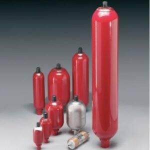
A bladder accumulator consists of a fluid section and a gas section with the bladder acting as the gas-proof separation element. The fluid around the bladder is connected to the hydraulic circuit so that the bladder accumulator draws in fluid when the pressure increases and the gas is compressed.
When the pressure drops, the compressed gas expands and forces the stored fluid into the circuit.
Available on backorder
Sale
HYDAC Standard Bladder Accumulator (SB 330-2.5 A 1/112 U-330 A 050 )
£1,171.20
A bladder accumulator consists of a fluid section and a gas section with the bladder acting as the gas-proof separation element. The fluid around the bladder is connected to the hydraulic circuit so that the bladder accumulator draws in fluid when the pressure increases and the gas is compressed.
When the pressure drops, the compressed gas expands and forces the stored fluid into the circuit.
Available on backorder
Sale
HYDAC Standard Bladder Accumulator (SB 330-20- A 1/112 U-330 A 050 )
£2,548.80
A bladder accumulator consists of a fluid section and a gas section with the bladder acting as the gas-proof separation element. The fluid around the bladder is connected to the hydraulic circuit so that the bladder accumulator draws in fluid when the pressure increases and the gas is compressed.
When the pressure drops, the compressed gas expands and forces the stored fluid into the circuit.
Available on backorder
HYDAC Standard Bladder Accumulator (SB 330-24- A 1/112 U-330 A 050 )
A bladder accumulator consists of a fluid section and a gas section with the bladder acting as the gas-proof separation element. The fluid around the bladder is connected to the hydraulic circuit so that the bladder accumulator draws in fluid when the pressure increases and the gas is compressed.
When the pressure drops, the compressed gas expands and forces the stored fluid into the circuit.
Available on backorder
Sale
HYDAC Standard Bladder Accumulator (SB 330-32- A 1/112 U-330 A 050 )
£2,997.60
A bladder accumulator consists of a fluid section and a gas section with the bladder acting as the gas-proof separation element. The fluid around the bladder is connected to the hydraulic circuit so that the bladder accumulator draws in fluid when the pressure increases and the gas is compressed.
When the pressure drops, the compressed gas expands and forces the stored fluid into the circuit.
Available on backorder
Sale
HYDAC Standard Bladder Accumulator (SB 330-4 A 1/112 U-330 A 050 )
£1,209.60
A bladder accumulator consists of a fluid section and a gas section with the bladder acting as the gas-proof separation element. The fluid around the bladder is connected to the hydraulic circuit so that the bladder accumulator draws in fluid when the pressure increases and the gas is compressed.
When the pressure drops, the compressed gas expands and forces the stored fluid into the circuit.
Available on backorder
Sale
HYDAC Standard Bladder Accumulator (SB 330-50- A 1/112 U-330 A 050 )
£3,864.00
A bladder accumulator consists of a fluid section and a gas section with the bladder acting as the gas-proof separation element. The fluid around the bladder is connected to the hydraulic circuit so that the bladder accumulator draws in fluid when the pressure increases and the gas is compressed.
When the pressure drops, the compressed gas expands and forces the stored fluid into the circuit.
Available on backorder
HYDAC Standard Bladder Accumulator (SB 330-6- A 1/112 U-330 A 050 )
A bladder accumulator consists of a fluid section and a gas section with the bladder acting as the gas-proof separation element. The fluid around the bladder is connected to the hydraulic circuit so that the bladder accumulator draws in fluid when the pressure increases and the gas is compressed.
When the pressure drops, the compressed gas expands and forces the stored fluid into the circuit.
Available on backorder
Sale
OLAER/PARKER Standard Bladder Accumulator (EHV05-350)
£842.40
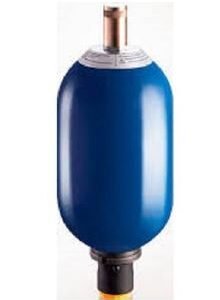
The EHV bladder accumulator offers a reliable and efficient solution for storing energy under pressure. Utilizing comprehensive tools and resources including an applications database, CAD/CAM, finite element analysis, reliability studies and simulation we have optimized the design and performance of the accumulator. Parker Olaer bladder accumulators are suitable for use in more than 35 countries (all hydraulic accumulators for Europe are CE marked) and they can meet an extensive range of international and industry approvals. The EHV Series bladder accumulator comes with an O-ring seal fluid port and 7/8” UNF gas connection as standard however other options are available.
Available on backorder
Sale
OLAER/PARKER Standard Bladder Accumulator (EHV10-330/00)
£856.80
The EHV bladder accumulator offers a reliable and efficient solution for storing energy under pressure. Utilizing comprehensive tools and resources including an applications database, CAD/CAM, finite element analysis, reliability studies and simulation we have optimized the design and performance of the accumulator. Parker Olaer bladder accumulators are suitable for use in more than 35 countries (all hydraulic accumulators for Europe are CE marked) and they can meet an extensive range of international and industry approvals. The EHV Series bladder accumulator comes with an O-ring seal fluid port and 7/8” UNF gas connection as standard however other options are available.
Available on backorder
OLAER/PARKER Standard Bladder Accumulator (EHV12-330/90)
The EHV bladder accumulator offers a reliable and efficient solution for storing energy under pressure. Utilizing comprehensive tools and resources including an applications database, CAD/CAM, finite element analysis, reliability studies and simulation we have optimized the design and performance of the accumulator. Parker Olaer bladder accumulators are suitable for use in more than 35 countries (all hydraulic accumulators for Europe are CE marked) and they can meet an extensive range of international and industry approvals. The EHV Series bladder accumulator comes with an O-ring seal fluid port and 7/8” UNF gas connection as standard however other options are available.
Available on backorder
Sale
OLAER/PARKER Standard Bladder Accumulator (EHV2.5-350)389
£746.40
The EHV bladder accumulator offers a reliable and efficient solution for storing energy under pressure. Utilizing comprehensive tools and resources including an applications database, CAD/CAM, finite element analysis, reliability studies and simulation we have optimized the design and performance of the accumulator. Parker Olaer bladder accumulators are suitable for use in more than 35 countries (all hydraulic accumulators for Europe are CE marked) and they can meet an extensive range of international and industry approvals. The EHV Series bladder accumulator comes with an O-ring seal fluid port and 7/8” UNF gas connection as standard however other options are available.