Available on backorder
SUN HYDRAULICS Pilot-operated, balanced poppet relief valve (RPESLWN)
£292.80
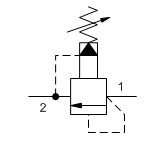
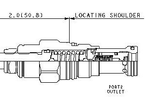
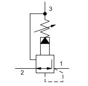
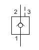
Pilot-operated, balanced-poppet relief cartridges are normally closed pressure regulating valves. When the pressure at the inlet (port 1) reaches the valve setting, the valve starts to open to tank (port 2), throttling flow to regulate the pressure. These valves are accurate, smooth, quiet, fast, and have low pressure rise vs. flow.
- Because the modulating occurs inside the cartridge, these valves are immune to most of the problems associated with cavitation, namely noise and manifold erosion.
- Will accept maximum pressure at port 2; suitable for use in cross port relief circuits.
- Valve is relatively insensitive to varying oil temperatures and oil borne contamination.
- Main stage orifice is protected by a 150-micron stainless steel screen.
Available on backorder
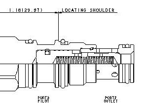
SUN HYDRAULICS Pilot-operated, pressure reducing main stage with integral T-8A control cavity (PBFB8WN)
£412.80
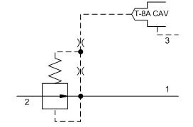
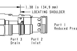
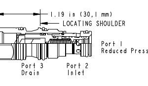
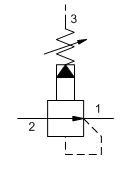
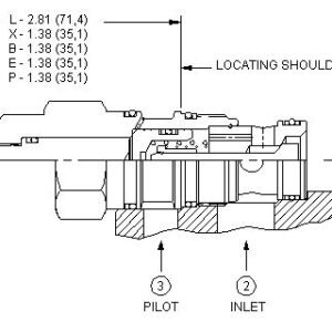
This valve is a normally open modulating element that incorporates an integral pilot control cavity. The pilot control cavity will accept any T-8A pressure control cartridge. The valve reduces a high primary pressure at the inlet (port 2) to a constant reduced pressure at port 1. The pilot cartridge's setting determines the difference in pressure between reduced pressure (port 1) and the drain (port 3).
- All three-port pressure reducing and reducing/relieving cartridges are physically interchangeable (i.e. same flow path, same cavity for a given frame size). When considering mounting configurations, it is sometimes recommended that a full capacity return line (port 3) be used with reducing/relieving cartridges.
- Full reverse flow from reduced pressure (port 1) to inlet (port 2) may cause the main spool to close. If reverse free flow is required in the circuit, consider adding a separate check valve to the circuit.
- Main stage orifice is protected by a 150 micron stainless steel screen.
- Pilot operated valves exhibit very low dead-band transition between reducing and relieving modes.
Available on backorder

SUN HYDRAULICS Pilot-operated, pressure reducing main stage with integral T-8A control cavity(PBDB8WN)
£295.20
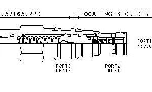
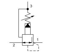
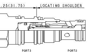
This valve is a normally open modulating element that incorporates an integral pilot control cavity. The pilot control cavity will accept any T-8A pressure control cartridge. The valve reduces a high primary pressure at the inlet (port 2) to a constant reduced pressure at port 1. The pilot cartridge's setting determines the difference in pressure between reduced pressure (port 1) and the drain (port 3).
- Full reverse flow from reduced pressure (port 1) to inlet (port 2) may cause the main spool to close. If reverse free flow is required in the circuit, consider adding a separate check valve to the circuit.
- Main stage orifice is protected by a 150 micron stainless steel screen.
- Pilot operated valves exhibit very low dead-band transition between reducing and relieving modes.
Available on backorder
SUN HYDRAULICS Pilot-operated, pressure reducing valve (PBBBLBN)
£271.20
Pilot-operated, pressure reducing valves reduce a high primary pressure at the inlet (port 2) to a constant reduced pressure at port 1, allowing circuits with multiple pressure requirements to be operated using a single pump.
- Full reverse flow from reduced pressure (port 1) to inlet (port 2) may cause the main spool to close. If reverse free flow is required in the circuit, consider adding a separate check valve to the circuit.
- Minimum setting is 75 psi (5 bar) for all spring ranges.
- Pilot operated valves exhibit exceptionally flat pressure/flow characteristics, are very stable and have low hysteresis.
- Pressure at port 3 is directly additive to the valve setting at a 1:1 ratio and should not exceed 5000 psi (350 bar).
Available on backorder


SUN HYDRAULICS Pilot-operated, pressure reducing valve(PBBBLWN)
£247.20
Pilot-operated, pressure reducing valves reduce a high primary pressure at the inlet (port 2) to a constant reduced pressure at port 1, allowing circuits with multiple pressure requirements to be operated using a single pump.
- Full reverse flow from reduced pressure (port 1) to inlet (port 2) may cause the main spool to close. If reverse free flow is required in the circuit, consider adding a separate check valve to the circuit.
- Minimum setting is 75 psi (5 bar) for all spring ranges.
- Pilot operated valves exhibit exceptionally flat pressure/flow characteristics, are very stable and have low hysteresis.
- Pressure at port 3 is directly additive to the valve setting at a 1:1 ratio and should not exceed 5000 psi (350 bar).
- Recommended maximum inlet pressure is determined by the adjustment range. Ranges A, B, N, and Q are tested with a 3000 psi (210 bar) maximum differential between inlet and reduced pressure. Range W is tested with 5000 psi (350 bar) of inlet pressure.
Available on backorder

SUN HYDRAULICS Pilot-operated, pressure reducing/relieving valve(PPBBLAN)
£328.80
Pilot-operated, pressure reducing/relieving valves reduce a high primary pressure at the inlet (port 2) to a constant reduced pressure at port 1, with a full-flow relief function from port 1 to tank (port 3).
- All three-port pressure reducing and reducing/relieving cartridges are physically interchangeable (i.e. same flow path, same cavity for a given frame size). When considering mounting configurations, it is sometimes recommended that a full capacity return line (port 3) be used with reducing/relieving cartridges.
- Full reverse flow from reduced pressure (port 1) to inlet (port 2) may cause the main spool to close. If reverse free flow is required in the circuit, consider adding a separate check valve to the circuit.
- If pilot flow consumption is critical, consider using direct acting reducing/relieving valves.
Available on backorder

SUN HYDRAULICS Pilot-operated, pressure reducing/relieving valve(PPFBLAN)
£475.20
Pilot-operated, pressure reducing/relieving valves reduce a high primary pressure at the inlet (port 2) to a constant reduced pressure at port 1, with a full-flow relief function from port 1 to tank (port 3).
- Pressure at port 3 is directly additive to the valve setting at a 1:1 ratio and should not exceed 3000 psi (210 bar).
- Maximum pressure at port 3 should be limited to 3000 psi (210 bar).
- Recommended maximum inlet pressure is determined by the adjustment range. Ranges D, E, N, and Q are tested with a 2000 psi (140 bar) maximum differential between inlet and reduced pressure. Ranges A, B, and H are tested with a 3000 psi (210 bar) maximum differential between inlet and reduced pressure. Ranges C and W are tested with 5000 psi (350 bar) of inlet pressure.
- Pilot operated valves exhibit exceptionally flat pressure/flow characteristics, are very stable and have low hysteresis.
Available on backorder
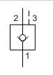
SUN HYDRAULICS Pilot-to-close check valve (CODAXAN)
£199.20This valve is a spring biased closed, pilot-to-close check cartridge that has a 1.8:1 pilot ratio. The valve allows flow from port 1 to port 2 and blocks reverse flow. Pressure at the pilot port opposes pressure at port 1 at a ratio of 1.8:1. This valve is most often used in regeneration circuits.
- Minimum clearances between the spool and sleeve and a seal on the pilot piston diameter significantly reduce the potential for silting.
- Nominal pilot ratio is 1.8:1. This means that a pressure of 1000 psi (70 bar) at the pilot port will close a valve against a pressure of 1800 psi (125 bar) at port 1. Any decay or loss of pilot pressure could allow the valve to open, even if it is a momentary decay or loss.
- Pressure at the port 2 area directly opposes pilot pressure.
- Reverse flow through the valve from port 2 to port 1 is not possible under any condition.
- With equal pressures at all ports the valve is closed.
Available on backorder
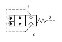

SUN HYDRAULICS Pilot-to-close, spring-biased closed, unbalanced poppet logic element (LODCXDN)
£223.20
These unbalanced, pilot-to-close logic valves are 2-way switching elements that are spring biased closed. Pressure at either work port 1 or 2 will oppose the spring and tend to open the valve while pressure at port 3 will tend to close it. The force generated at port 3, plus the spring force, must be greater than the sum of the forces acting at port 1 and port 2 for the valve to remain closed. NOTE: The pilot area (port 3) is 1.8 times the area at port 1 and 2.25 times the area at port 2.
- These valves have positive seals between port 2 and the pilot area.
- Because these valves are unbalanced, operation is pressure dependent. Opening and closing of the poppet are functions of the force balances on three areas: Port 1 = 100%, Port 2 = 80%, and the Pilot Area = 180%.
- These valves are pressure responsive at all ports, therefore it is essential to consider all aspects of system operation through a complete cycle. Pressure changes at any one port may cause a valve to switch from a closed to an open position, or vice versa. All possible pressure changes in the complete circuit must be considered to assure a safe, functional system design.
- All ports will accept 5000 psi (350 bar).
Available on backorder

SUN HYDRAULICS Pilot-to-open check valve with sealed pilot (CKEDXCN)
£244.80
This valve is a pilot to open check valve. It has a sealed pilot, a steel seat, and is non-vented. It allows free flow from the valve (port 2) to the load (port 1) and blocks flow in the opposite direction. Pressure at the pilot (port 3) will open the valve from port 1 to port 2. Pilot pressure needed at port 3 to open the valve is directly proportional to the load pressure at port 1. Pressure at port 2 directly opposes pilot pressure.
- For models with manual load release control option, turn load release clockwise to release load.
- This 3 port pilot-to-open check valve and 3 port counterbalance valves are physically interchangeable (i.e. same cavities, same flow path for a given frame size). However, cartridge extension dimensions from the mounting surface may vary.
- Provides hose break protection, prevents loads from drifting and positively locks pressurized loads.
- Extremely low leakage. The seat and poppet are heat treated for long life. If the load drifts due to the valve, the seat has probably been damaged by contamination and the valve should be replaced.
- Sealed pilot for use in circuits where cross port leakage is undesirable.
Available on backorder

SUN HYDRAULICS Pilot-to-open check valve with sealed pilot (CKEDXEN)
£244.80
This valve is a pilot to open check valve. It has a sealed pilot, a steel seat, and is non-vented. It allows free flow from the valve (port 2) to the load (port 1) and blocks flow in the opposite direction. Pressure at the pilot (port 3) will open the valve from port 1 to port 2. Pilot pressure needed at port 3 to open the valve is directly proportional to the load pressure at port 1. Pressure at port 2 directly opposes pilot pressure.
- For models with manual load release control option, turn load release clockwise to release load.
- This 3 port pilot-to-open check valve and 3 port counterbalance valves are physically interchangeable (i.e. same cavities, same flow path for a given frame size). However, cartridge extension dimensions from the mounting surface may vary.
- Provides hose break protection, prevents loads from drifting and positively locks pressurized loads.
Available on backorder

SUN HYDRAULICS Pilot-to-open check valve with sealed pilot(CKBDXCN)
£158.40
This valve is a pilot to open check valve. It has a sealed pilot, a steel seat, and is non-vented. It allows free flow from the valve (port 2) to the load (port 1) and blocks flow in the opposite direction. Pressure at the pilot (port 3) will open the valve from port 1 to port 2. Pilot pressure needed at port 3 to open the valve is directly proportional to the load pressure at port 1. Pressure at port 2 directly opposes pilot pressure.
- Provides hose break protection, prevents loads from drifting and positively locks pressurized loads.
- Extremely low leakage. The seat and poppet are heat treated for long life. If the load drifts due to the valve, the seat has probably been damaged by contamination and the valve should be replaced.
- Sealed pilot for use in circuits where cross port leakage is undesirable.
- Note: Available only with 30 psi or 75 psi (2 bar or 5 bar) check valve cracking pressures.