Available on backorder

SUN HYDRAULICS Kick-down, pilot-operated, balanced piston relief valve (RQIBLAN)
£777.60
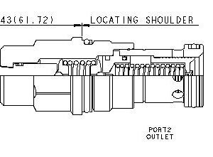
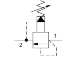
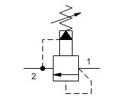
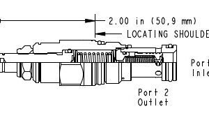
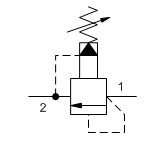
Kick-down relief cartridges act similar to a circuit breaker in an electrical system. The valves will kick completely open and remain open once the pressure at the inlet (port 1) exceeds the valve settting, creating an unrestricted flow path from port 1 to tank (port 2). The valve remains open as long as the pressure at port 1 exceeds the pressure at port 2. To reset the valve, flow from port 1 to port 2 must cease and pressure at port 2 must be equal to or greater than the pressure at port 1.
- All 2-port relief cartridges (except pilot reliefs) are physically and functionally interchangeable (same flow path, same cavity for a given frame size).
- To reset valve, flow through the cartridge must cease.
- Main stage orifice is protected by a 150-micron stainless steel screen.
- Not suitable for use in load holding applications.
Available on backorder
SUN HYDRAULICS Pilot-operated, balanced piston relief valve (RPEC-KCN)
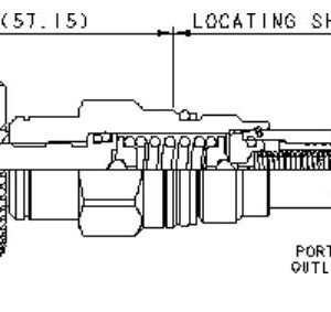
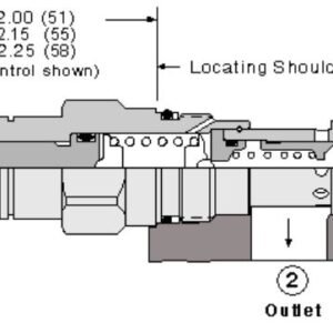
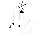
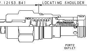
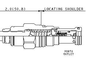
Pilot-operated, balanced-piston relief cartridges are normally closed pressure regulating valves. When the pressure at the inlet (port 1) reaches the valve setting, the valve starts to open to tank (port 2), throttling flow to regulate the pressure. These valves are accurate, have low pressure rise vs. flow, they are smooth and quiet, and are moderately fast.
- All 2-port relief cartridges (except pilot reliefs) are physically and functionally interchangeable (same flow path, same cavity for a given frame size).
- Will accept maximum pressure at port 2; suitable for use in cross port relief circuits. If used in cross port relief circuits, consider spool leakage.
- Main stage orifice is protected by a 150-micron stainless steel screen.
- Not suitable for use in load holding applications due to spool leakage.
- Back pressure on the tank port (port 2) is directly additive to the valve setting at a 1:1 ratio.
- Cartridges configured with EPDM seals are for use in systems with phosphate ester fluids. Exposure to petroleum based fluids, greases and lubricants will damage the seals.
- W and Y controls (where applicable) can be specified with or without a special setting. When no special setting is specified, the valve is adjustable throughout its full range using the W or Y control. When a special setting is specified, this setting represents the maximum setting of the valve.
- Corrosion resistant cartridge valves are intended for use in corrosive environments and are identified by the model code suffix /AP for external stainless steel components, or /LH for external zinc-nickel plated components. See the CONFIGURATION section for all options. For further details, please see the Materials of Construction page located under TECH RESOURCES.
- Incorporates the Sun floating style construction to minimize the possibility of internal parts binding due to excessive installation torque and/or cavity/cartridge machining variations.
Available on backorder
SUN HYDRAULICS Pilot-operated, balanced piston relief valve (RPEC-LAN)
Pilot-operated, balanced-piston relief cartridges are normally closed pressure regulating valves. When the pressure at the inlet (port 1) reaches the valve setting, the valve starts to open to tank (port 2), throttling flow to regulate the pressure. These valves are accurate, have low pressure rise vs. flow, they are smooth and quiet, and are moderately fast.
- All 2-port relief cartridges (except pilot reliefs) are physically and functionally interchangeable (same flow path, same cavity for a given frame size).
- Will accept maximum pressure at port 2; suitable for use in cross port relief circuits. If used in cross port relief circuits, consider spool leakage.
- Main stage orifice is protected by a 150-micron stainless steel screen.
- Not suitable for use in load holding applications due to spool leakage.
- Back pressure on the tank port (port 2) is directly additive to the valve setting at a 1:1 ratio.
- Cartridges configured with EPDM seals are for use in systems with phosphate ester fluids. Exposure to petroleum based fluids, greases and lubricants will damage the seals.
- W and Y controls (where applicable) can be specified with or without a special setting. When no special setting is specified, the valve is adjustable throughout its full range using the W or Y control. When a special setting is specified, this setting represents the maximum setting of the valve.
- Corrosion resistant cartridge valves are intended for use in corrosive environments and are identified by the model code suffix /AP for external stainless steel components, or /LH for external zinc-nickel plated components. See the CONFIGURATION section for all options. For further details, please see the Materials of Construction page located under TECH RESOURCES.
- Incorporates the Sun floating style construction to minimize the possibility of internal parts binding due to excessive installation torque and/or cavity/cartridge machining variations.
Available on backorder
SUN HYDRAULICS Pilot-operated, balanced piston relief valve (RPEC-LCN)
Pilot-operated, balanced-piston relief cartridges are normally closed pressure regulating valves. When the pressure at the inlet (port 1) reaches the valve setting, the valve starts to open to tank (port 2), throttling flow to regulate the pressure. These valves are accurate, have low pressure rise vs. flow, they are smooth and quiet, and are moderately fast.
- All 2-port relief cartridges (except pilot reliefs) are physically and functionally interchangeable (same flow path, same cavity for a given frame size).
- Will accept maximum pressure at port 2; suitable for use in cross port relief circuits. If used in cross port relief circuits, consider spool leakage.
- Main stage orifice is protected by a 150-micron stainless steel screen.
- Not suitable for use in load holding applications due to spool leakage.
- Back pressure on the tank port (port 2) is directly additive to the valve setting at a 1:1 ratio.
- Cartridges configured with EPDM seals are for use in systems with phosphate ester fluids. Exposure to petroleum based fluids, greases and lubricants will damage the seals.
- W and Y controls (where applicable) can be specified with or without a special setting. When no special setting is specified, the valve is adjustable throughout its full range using the W or Y control. When a special setting is specified, this setting represents the maximum setting of the valve.
- Corrosion resistant cartridge valves are intended for use in corrosive environments and are identified by the model code suffix /AP for external stainless steel components, or /LH for external zinc-nickel plated components. See the CONFIGURATION section for all options. For further details, please see the Materials of Construction page located under TECH RESOURCES.
- Incorporates the Sun floating style construction to minimize the possibility of internal parts binding due to excessive installation torque and/or cavity/cartridge machining variations.
Available on backorder
SUN HYDRAULICS Pilot-operated, balanced piston relief valve (RPEC-LWN)
Pilot-operated, balanced-piston relief cartridges are normally closed pressure regulating valves. When the pressure at the inlet (port 1) reaches the valve setting, the valve starts to open to tank (port 2), throttling flow to regulate the pressure. These valves are accurate, have low pressure rise vs. flow, they are smooth and quiet, and are moderately fast.
- All 2-port relief cartridges (except pilot reliefs) are physically and functionally interchangeable (same flow path, same cavity for a given frame size).
- Will accept maximum pressure at port 2; suitable for use in cross port relief circuits. If used in cross port relief circuits, consider spool leakage.
- Main stage orifice is protected by a 150-micron stainless steel screen.
- Not suitable for use in load holding applications due to spool leakage.
- Back pressure on the tank port (port 2) is directly additive to the valve setting at a 1:1 ratio.
- Cartridges configured with EPDM seals are for use in systems with phosphate ester fluids. Exposure to petroleum based fluids, greases and lubricants will damage the seals.
- W and Y controls (where applicable) can be specified with or without a special setting. When no special setting is specified, the valve is adjustable throughout its full range using the W or Y control. When a special setting is specified, this setting represents the maximum setting of the valve.
- Corrosion resistant cartridge valves are intended for use in corrosive environments and are identified by the model code suffix /AP for external stainless steel components, or /LH for external zinc-nickel plated components. See the CONFIGURATION section for all options. For further details, please see the Materials of Construction page located under TECH RESOURCES.
- Incorporates the Sun floating style construction to minimize the possibility of internal parts binding due to excessive installation torque and/or cavity/cartridge machining variations.
Available on backorder
SUN HYDRAULICS Pilot-operated, balanced piston relief valve (RPECLEN-FAU)
£343.20
Pilot-operated, balanced-piston relief cartridges are normally closed pressure regulating valves. When the pressure at the inlet (port 1) reaches the valve setting, the valve starts to open to tank (port 2), throttling flow to regulate the pressure. These valves are accurate, have low pressure rise vs. flow, they are smooth and quiet, and are moderately fast.
- All 2-port relief cartridges (except pilot reliefs) are physically and functionally interchangeable (same flow path, same cavity for a given frame size).
- Cartridges configured with EPDM seals are for use in systems with phosphate ester fluids. Exposure to petroleum based fluids, greases and lubricants will damage the seals.
- Will accept maximum pressure at port 2; suitable for use in cross port relief circuits. If used in cross port relief circuits, consider spool leakage.
- Main stage orifice is protected by a 150-micron stainless steel screen.
- Not suitable for use in load holding applications due to spool leakage.
Available on backorder
SUN HYDRAULICS Pilot-operated, balanced piston relief valve (RPGCLAN)
£336.00
Pilot-operated, balanced-piston relief cartridges are normally closed pressure regulating valves. When the pressure at the inlet (port 1) reaches the valve setting, the valve starts to open to tank (port 2), throttling flow to regulate the pressure. These valves are accurate, have low pressure rise vs. flow, they are smooth and quiet, and are moderately fast.
- Will accept maximum pressure at port 2; suitable for use in cross port relief circuits. If used in cross port relief circuits, consider spool leakage.
- Main stage orifice is protected by a 150-micron stainless steel screen.
- Not suitable for use in load holding applications due to spool leakage.
- Back pressure on the tank port (port 2) is directly additive to the valve setting at a 1:1 ratio.
Available on backorder


SUN HYDRAULICS Pilot-operated, balanced poppet relief valve (RPESLAN)
£292.80
Pilot-operated, balanced-poppet relief cartridges are normally closed pressure regulating valves. When the pressure at the inlet (port 1) reaches the valve setting, the valve starts to open to tank (port 2), throttling flow to regulate the pressure. These valves are accurate, smooth, quiet, fast, and have low pressure rise vs. flow.
- Because the modulating occurs inside the cartridge, these valves are immune to most of the problems associated with cavitation, namely noise and manifold erosion.
- Will accept maximum pressure at port 2; suitable for use in cross port relief circuits.
- Valve is relatively insensitive to varying oil temperatures and oil borne contamination.
- Main stage orifice is protected by a 150-micron stainless steel screen.
- Suitable for use in load holding applications.
Available on backorder
SUN HYDRAULICS Pilot-operated, balanced poppet relief valve (RPESLWN)
£292.80
Pilot-operated, balanced-poppet relief cartridges are normally closed pressure regulating valves. When the pressure at the inlet (port 1) reaches the valve setting, the valve starts to open to tank (port 2), throttling flow to regulate the pressure. These valves are accurate, smooth, quiet, fast, and have low pressure rise vs. flow.
- Because the modulating occurs inside the cartridge, these valves are immune to most of the problems associated with cavitation, namely noise and manifold erosion.
- Will accept maximum pressure at port 2; suitable for use in cross port relief circuits.
- Valve is relatively insensitive to varying oil temperatures and oil borne contamination.
- Main stage orifice is protected by a 150-micron stainless steel screen.
Available on backorder
SUN HYDRAULICS Solenoid-operated adjustable relief valve (RVCK-LJN224)
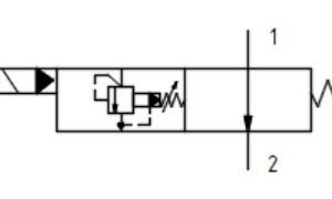
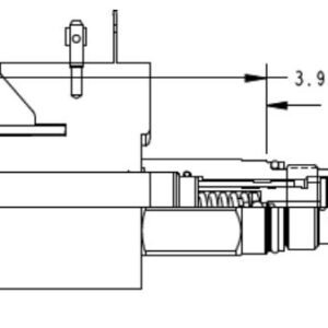
This FLeX Series solenoid-operated, 2-stage, balanced relief cartridge is a pressure regulating valve. The valve is normally vented. When vented (de-energized), the pressure drop from the inlet (port 1) to tank (port 2) is typically 100 psi.Energizing the solenoid activates the relief function. In relief mode, the valve opens to tank (port 2), throttling flow to regulate the pressure when the pressure at the inlet (port 1) reaches the valve setting. The setting is adjustable with an adjust screw.
- Designed and tested to 10-million operational cycles at full-rated pressure.
- Exceeds new NFPA test standard T2.6.1 R2014 for fatigue and burst pressure ratings.
- Higher flow rates than competing valves of similar size.
- All configurations of this valve include zinc-nickel plating as standard for 1000-hour salt fog protection.
- Coil connector options offer ratings up to IP69K. See individual coil product pages for details.
- This cartridge utilizes both 740 Series high-power and 747 Series hazardous location coils.
- Back pressure on the tank port (port 2) is directly additive to the valve setting at a 1:1 ratio.
- Main stage orifice is protected by a 150-micron stainless steel screen.
- Will accept maximum pressure at port 2.
- All configurations of this valve are assembled with a non-removable adjust screw.
- FLeX Series relief valves are fully compatible with the XMD Expandable Mobile Drivers from Sun.
Available on backorder
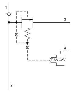
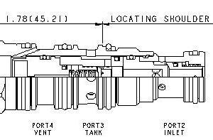
SUN HYDRAULICS Ventable, pilot-operated, balanced piston relief main stage with integral T-8A control cavity – before check (HVCA8DN)
£535.20
The relief-before-check cartridge is a CavitySaver™ (multi-function) valve incorporating a normally closed, balanced piston modulating element tee'd in before a check function. The valve incorporates an integral pilot control cavity. The pilot control cavity will accept any T-8A pressure control cartridge. When the pressure at the inlet (port 2) reaches the pilot control valve setting, the modulating element starts to open to tank (port 3), throttling flow to regulate the pressure. The T-8A pilot section is drained to port 4. The check valve flow is from the inlet (port 2) to the system port (port1).
- Note! This valve deviates from Sun's normal flow path for relief valves. It is probably not useable in current Sun relief manifolds.
- Cartridges configured with EPDM seals are for use in systems with phosphate ester fluids. Exposure to petroleum based fluids, greases and lubricants will damage the seals.
- The main stage orifice is protected against contamination.
- The check portion of the valve has a maximum leakage rate of less than 1 drop/minute (0,07 cc/min).
- One purpose of this dual function cartridge is to offer pump isolation and relief protection in single and/or multiple pump circuits. Another purpose is to act as a main stage in an accumulator sense, pump unload circuit.
- NOTE: With the -8 control option, the main stage valve should first be installed to the correct torque value. The T-8A pilot control valve should then be installed into the main stage valve to its required torque value.
Available on backorder
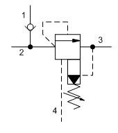
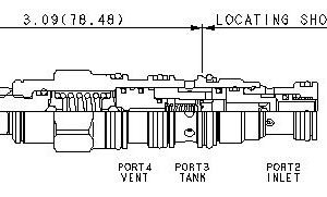
SUN HYDRAULICS Ventable, pilot-operated, balanced piston relief valve – before check (HVCALAN)
£480.00
The ventable relief-before-check cartridge is a CavitySaver™ (multi-function) valve incorporating a ventable, pilot-operated, balanced piston relief tee'd in before a check function. When the pressure at the inlet (port 2) reaches the relief valve setting, the valve starts to open to tank (port 3), throttling flow to regulate the pressure. The check valve flow is from the inlet (port 2) to the system port (port1). The valve includes a vent port (port 4) that connects between the main piston and pilot stage to provide for remote control by other pilot or 2-way valves.
These valves are accurate, have low pressure rise vs. flow, are smooth, quiet, and are moderately fast.
- Note! This valve deviates from Sun's normal flow path for relief valves. It is probably not useable in current Sun relief manifolds.
- Minimum setting is 75 psi (5 bar) for all spring ranges.
- Back pressure at port 3 (tank) is directly additive to the valve setting at a 1:1 ratio.
- The check portion of the valve has a maximum leakage rate of less than 1 drop/minute (0,07 cc/min).