Available on backorder
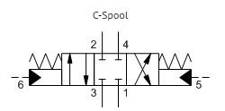
SUN HYDRAULICS 4-way, 3-position, pilot-to-shift directional valve(DCDCXCN)
£835.20
Three-position, 4-way directional cartridges are spring-centered, 6-port directional valves that can be configured from a choice of spool options. The supply port is port 3 and all ports will accept 5000 psi (350 bar). Capacity for these pilot-to-shift valves is dependent on the spool type specified.
- All ports will accept 5000 psi (350 bar), including the x and y pilot ports (port 5 and port 6).
- The reason for the different capacities, or performance limits, for the different spool configurations are flow forces. Flow forces are proportional to flow and pressure drop. Typically, they resist the opening of a passage. Spool configurations that open passages as they spring center are the most susceptible. If the flow forces due to the flow and pressure conditions exceed the centering spring force the valve may not shift completely. Higher flows may be used at lower pressures.
- Leakage listed in technical data is for each path.
- The pilot ports, 5 and 6, are positively sealed from the work ports.
Available on backorder

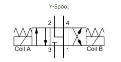
SUN HYDRAULICS 4-way, 3-position, solenoid-operated directional spool valve (DNDCXCN)
£576.00
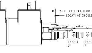
This direct acting, solenoid-operated, 4-way, 3-position spool valve is spring centered to the neutral position. When coil A is energized, the flow is from port 3 (P) to port 2 (A) and from port 4 (B) to port 1 (T). When coil B is energized, the flow is from port 3 to port 4 and from port 2 to port 1.
- The solenoid tube assembly is fatigue rated for 5000 psi (350 bar) service.
- This valve is direct actuated and requires no minimum hydraulic pressure for operation.
- In differential flow circuits, the higher return flow should be directed through port 2 (A) to port 1 (T).
Out of stock
SUN HYDRAULICS 4-way, 3-position, solenoid-operated directional spool valve (DNDCXYN224)
£780.00
This direct acting, solenoid-operated, 4-way, 3-position spool valve is spring centered to the neutral position. When coil A is energized, the flow is from port 3 (P) to port 2 (A) and from port 4 (B) to port 1 (T). When coil B is energized, the flow is from port 3 to port 4 and from port 2 to port 1.
- The solenoid tube assembly is fatigue rated for 5000 psi (350 bar) service.
- This valve is direct actuated and requires no minimum hydraulic pressure for operation.
- In differential flow circuits, the higher return flow should be directed through port 2 (A) to port 1 (T).
- Cartridges configured with EPDM seals are for use in systems with phosphate ester fluids. Exposure to petroleum based fluids, greases and lubricants will damage the seals.
Available on backorder
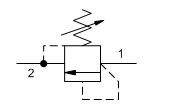
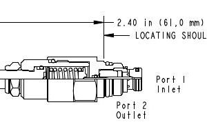
SUN HYDRAULICS 4.5:1 pilot ratio, standard capacity counterbalance valve (CBEGLJN)
£386.40
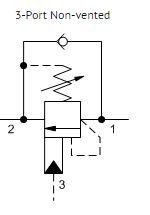
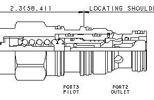
Counterbalance valves with pilot assist are meant to control an overrunning load. The check valve allows free flow from the directional valve (port 2) to the load (port 1) while a direct-acting, pilot-assisted relief valve controls flow from port 1 to port 2. Pilot assist at port 3 lowers the effective setting of the relief valve at a rate determined by the pilot ratio.
Other names for this valve include motion control valve and over-center valve.
- Counterbalance valves should be set at least 1.3 times the maximum load induced pressure.
- Turn adjustment clockwise to decrease setting and release load.
- Full clockwise setting is less than 200 psi (14 bar).
- Backpressure at port 2 adds to the effective relief setting at a ratio of 1 plus the pilot ratio times the backpressure.
- Reseat exceeds 85% of set pressure when the valve is standard set. Settings lower than the standard set pressure may result in lower reseat percentages.
Available on backorder


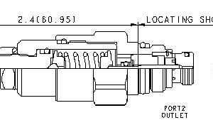
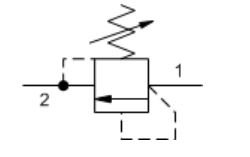
SUN HYDRAULICS 4.5:1 pilot ratio, standard capacity counterbalance valve(CBCGLJN) (Copy)
£264.00Counterbalance valves with pilot assist are meant to control an overrunning load. The check valve allows free flow from the directional valve (port 2) to the load (port 1) while a direct-acting, pilot-assisted relief valve controls flow from port 1 to port 2. Pilot assist at port 3 lowers the effective setting of the relief valve at a rate determined by the pilot ratio. Other names for this valve include motion control valve and over-center valve.
- Counterbalance valves should be set at least 1.3 times the maximum load induced pressure.
- Turn adjustment clockwise to decrease setting and release load.
- Full clockwise setting is less than 200 psi (14 bar).
- Backpressure at port 2 adds to the effective relief setting at a ratio of 1 plus the pilot ratio times the backpressure.
Available on backorder


SUN HYDRAULICS 4.5:1 pilot ratio, standard capacity counterbalance valve(CBGGLJN)
£770.40
Counterbalance valves with pilot assist are meant to control an overrunning load. The check valve allows free flow from the directional valve (port 2) to the load (port 1) while a direct-acting, pilot-assisted relief valve controls flow from port 1 to port 2. Pilot assist at port 3 lowers the effective setting of the relief valve at a rate determined by the pilot ratio.
Other names for this valve include motion control valve and over-center valve.
- Counterbalance valves should be set at least 1.3 times the maximum load induced pressure.
- Turn adjustment clockwise to decrease setting and release load.
- Full clockwise setting is less than 200 psi (14 bar).
- Backpressure at port 2 adds to the effective relief setting at a ratio of 1 plus the pilot ratio times the backpressure.
Available on backorder


SUN HYDRAULICS Balanced, load control valve(MBIMXIN)
£2,064.00
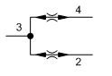
Balanced load control valves combine a balanced modulating element with a reverse flow check. The check valve allows free flow from the directional valve (port 2) to the load (port 1) while the pilot to open modulating element controls flow from port 1 to port 2. Pilot pressure at port 3 determines the flow setting.
- This valve has no relief function. Not even thermal expansion relief.
- Maximum valve leakage at reseat for I, K, M ranges is 5 drops/min. (0,3 cc/min.) at 200 psi (14 bar) below cracking pressure; E and G ranges is 3 cubic in/min. (50 cc/min.) at 50 psi (3,5 bar) below cracking pressure; H range is 3 cubic in/min. (50 cc/min.) at 75 psi (5 bar) below cracking pressure.
Available on backorder

SUN HYDRAULICS Closed center, flow divider-combiner valve (FSEAXAN)
£1,555.20
Closed-center flow divider/combiners are sliding-spool, pressure-compensated devices used to split flow in one direction and combine flow in the opposite direction. These valves may be used to accurately control two or more cylinders or hydraulic motors where bidirectional operation is required.
- All flow divider and divider/combiner cartridges are physically interchangeable (i.e. same flow path, same cavity for a given frame size).
- Operating characteristics cause the leg of the circuit with the greatest load to receive the higher percentage of flow in dividing mode. If a rigid mechanism is used to tie actuators together, the lead actuator may pull the lagging actuator and cause it to cavitate.
- In combining mode, compensating characteristics will cause the leg of the circuit with the lowest load to receive the higher percentage of flow. If a synchronization feature is not included, an additive accuracy error will be experienced with each full stroke of the actuator.
Available on backorder
SUN HYDRAULICS Direct-acting relief valve – pilot capacity (RBAELAN)
£268.80
Two-port, pilot-stage, direct-acting relief cartridges are fully adjustable, normally closed pressure regulating valves. When the pressure at port 1 (inlet) is sufficient to overcome the spring force (valve setting), a flow path is opened from port 1 to port 2 (tank).
- Utilizes the Sun T-8A 2-port cavity making it the ideal choice to use in conjunction with Sun's main stage pilot or vent-to-operate cartridges. Separate pilot lines are eliminated and only one cavity needs to be machined to accommodate both the control and primary function. Note: All 2-position, 2-way pilot stage control cartridges utilize the same cavity and are physically interchangeable. Functionality is the only consideration.
- Note: The main stage valve should first be installed to the correct torque value followed by the T-8A pilot control section into the main stage valve to its required torque value.
- Ports 1 and 2 may be pressured to 5000 psi (350 bar).
Available on backorder

SUN HYDRAULICS Direct-acting relief valve – pilot capacity(RBAELBN)
£268.80
Two-port, pilot-stage, direct-acting relief cartridges are fully adjustable, normally closed pressure regulating valves. When the pressure at port 1 (inlet) is sufficient to overcome the spring force (valve setting), a flow path is opened from port 1 to port 2 (tank).
- Utilizes the Sun T-8A 2-port cavity making it the ideal choice to use in conjunction with Sun's main stage pilot or vent-to-operate cartridges. Separate pilot lines are eliminated and only one cavity needs to be machined to accommodate both the control and primary function. Note: All 2-position, 2-way pilot stage control cartridges utilize the same cavity and are physically interchangeable. Functionality is the only consideration.
- Note: The main stage valve should first be installed to the correct torque value followed by the T-8A pilot control section into the main stage valve to its required torque value.
- Ports 1 and 2 may be pressured to 5000 psi (350 bar).
- Hardened poppet and seat provide consistent operation, low leakage rates and superior wear characteristics.
- Backpressure at port 2 (outlet) is directly additive to the pressure setting at port 1 (inlet).
Available on backorder

SUN HYDRAULICS Direct-acting relief valve (RDDA-LAN)
Direct-acting relief cartridges are normally closed, pressure-limiting valves used to protect hydraulic components from pressure transients. When the pressure at the inlet (port 1) reaches the valve setting, the valve starts to open to tank (port 2), throttling flow to limit the pressure rise. These valves are smooth and quiet, essentially zero leak, dirt tolerant, immune to silting and are very fast.
- All 2-port relief cartridges (except pilot reliefs) are physically and functionally interchangeable (same flow path, same cavity for a given frame size).
- Will accept maximum pressure at port 2; suitable for use in cross port relief circuits.
- The seals on the adjust screw are exposed to system pressure which means this valve can only be adjusted when the pressure is removed. The setting procedure is; check the setting, remove the pressure, adjust the valve, check the new setting.
- Valve is relatively insensitive to varying oil temperatures and oil borne contamination.
- Select a spring range where the desired relief setting is approximately mid-range to high between the minimum and maximum pressure to ensure maximum valve repeatability.
- Suitable for use in load holding applications.
- Back pressure on the tank port (port 2) is directly additive to the valve setting at a 1:1 ratio.
- Cartridges configured with EPDM seals are for use in systems with phosphate ester fluids. Exposure to petroleum based fluids, greases and lubricants will damage the seals.
- Incorporates the Sun floating style construction to minimize the possibility of internal parts binding due to excessive installation torque and/or cavity/cartridge machining variations.
Available on backorder
SUN HYDRAULICS Direct-acting relief valve (RDDA-LWN)
Direct-acting relief cartridges are normally closed, pressure-limiting valves used to protect hydraulic components from pressure transients. When the pressure at the inlet (port 1) reaches the valve setting, the valve starts to open to tank (port 2), throttling flow to limit the pressure rise. These valves are smooth and quiet, essentially zero leak, dirt tolerant, immune to silting and are very fast.
- All 2-port relief cartridges (except pilot reliefs) are physically and functionally interchangeable (same flow path, same cavity for a given frame size).
- Will accept maximum pressure at port 2; suitable for use in cross port relief circuits.
- The seals on the adjust screw are exposed to system pressure which means this valve can only be adjusted when the pressure is removed. The setting procedure is; check the setting, remove the pressure, adjust the valve, check the new setting.
- Valve is relatively insensitive to varying oil temperatures and oil borne contamination.
- Select a spring range where the desired relief setting is approximately mid-range to high between the minimum and maximum pressure to ensure maximum valve repeatability.
- Suitable for use in load holding applications.
- Back pressure on the tank port (port 2) is directly additive to the valve setting at a 1:1 ratio.
- Cartridges configured with EPDM seals are for use in systems with phosphate ester fluids. Exposure to petroleum based fluids, greases and lubricants will damage the seals.
- Incorporates the Sun floating style construction to minimize the possibility of internal parts binding due to excessive installation torque and/or cavity/cartridge machining variations.