Available on backorder

SUN HYDRAULICS Normally closed, balanced poppet, logic element with integral T-8A control cavity – vent-to-open (DKJR8HN)
£1,850.40
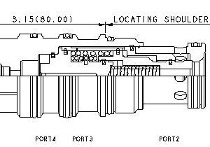
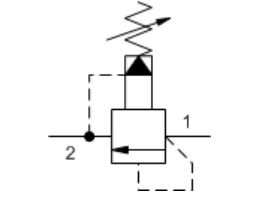
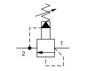
This is a normally closed, balanced poppet, switching element with an integral T-8A control cavity. With a 2-way valve in the closed position installed in the T-8A control cavity, the poppet remains closed. Opening the 2-way valve shifts the poppet to the open position, provided there is sufficient pressure at port 3.
- Unique balanced construction provides predictable switching with 5000 psi (350 bar) at port 1 and port 2. Switching will only occur when both a minimum pilot pressure of 400 psi (30 bar) is present and pilot control valve is open.
- These valves are hydraulically balanced between port 1 and port 2.
- Port 1 and port 2 are fully sealed from port 3 and port 4. Ports 3 and 4 are positively sealed.
- Any backpressure at the drain port is directly additive to the required pilot pressure for reliable operation.
- Leakage rate between port 1 and port 2 is very low, typically less than 10 drops/min. at 5000 psi (0,7 cc/min at 350 bar).
- Valve will reseat when the pilot pressure falls below 145 psi (10 bar).
Available on backorder
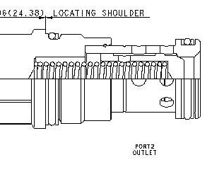
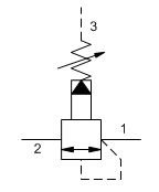
SUN HYDRAULICS Pilot-operated, balanced piston relief valve (RPEC-KCN)
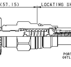
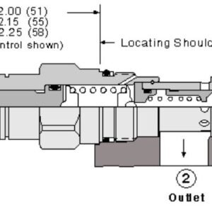
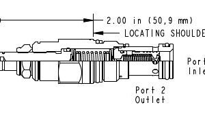
Pilot-operated, balanced-piston relief cartridges are normally closed pressure regulating valves. When the pressure at the inlet (port 1) reaches the valve setting, the valve starts to open to tank (port 2), throttling flow to regulate the pressure. These valves are accurate, have low pressure rise vs. flow, they are smooth and quiet, and are moderately fast.
- All 2-port relief cartridges (except pilot reliefs) are physically and functionally interchangeable (same flow path, same cavity for a given frame size).
- Will accept maximum pressure at port 2; suitable for use in cross port relief circuits. If used in cross port relief circuits, consider spool leakage.
- Main stage orifice is protected by a 150-micron stainless steel screen.
- Not suitable for use in load holding applications due to spool leakage.
- Back pressure on the tank port (port 2) is directly additive to the valve setting at a 1:1 ratio.
- Cartridges configured with EPDM seals are for use in systems with phosphate ester fluids. Exposure to petroleum based fluids, greases and lubricants will damage the seals.
- W and Y controls (where applicable) can be specified with or without a special setting. When no special setting is specified, the valve is adjustable throughout its full range using the W or Y control. When a special setting is specified, this setting represents the maximum setting of the valve.
- Corrosion resistant cartridge valves are intended for use in corrosive environments and are identified by the model code suffix /AP for external stainless steel components, or /LH for external zinc-nickel plated components. See the CONFIGURATION section for all options. For further details, please see the Materials of Construction page located under TECH RESOURCES.
- Incorporates the Sun floating style construction to minimize the possibility of internal parts binding due to excessive installation torque and/or cavity/cartridge machining variations.
Available on backorder
SUN HYDRAULICS Pilot-operated, balanced piston relief valve (RPEC-LAN)
Pilot-operated, balanced-piston relief cartridges are normally closed pressure regulating valves. When the pressure at the inlet (port 1) reaches the valve setting, the valve starts to open to tank (port 2), throttling flow to regulate the pressure. These valves are accurate, have low pressure rise vs. flow, they are smooth and quiet, and are moderately fast.
- All 2-port relief cartridges (except pilot reliefs) are physically and functionally interchangeable (same flow path, same cavity for a given frame size).
- Will accept maximum pressure at port 2; suitable for use in cross port relief circuits. If used in cross port relief circuits, consider spool leakage.
- Main stage orifice is protected by a 150-micron stainless steel screen.
- Not suitable for use in load holding applications due to spool leakage.
- Back pressure on the tank port (port 2) is directly additive to the valve setting at a 1:1 ratio.
- Cartridges configured with EPDM seals are for use in systems with phosphate ester fluids. Exposure to petroleum based fluids, greases and lubricants will damage the seals.
- W and Y controls (where applicable) can be specified with or without a special setting. When no special setting is specified, the valve is adjustable throughout its full range using the W or Y control. When a special setting is specified, this setting represents the maximum setting of the valve.
- Corrosion resistant cartridge valves are intended for use in corrosive environments and are identified by the model code suffix /AP for external stainless steel components, or /LH for external zinc-nickel plated components. See the CONFIGURATION section for all options. For further details, please see the Materials of Construction page located under TECH RESOURCES.
- Incorporates the Sun floating style construction to minimize the possibility of internal parts binding due to excessive installation torque and/or cavity/cartridge machining variations.
Available on backorder
SUN HYDRAULICS Pilot-operated, balanced piston relief valve (RPEC-LCN)
Pilot-operated, balanced-piston relief cartridges are normally closed pressure regulating valves. When the pressure at the inlet (port 1) reaches the valve setting, the valve starts to open to tank (port 2), throttling flow to regulate the pressure. These valves are accurate, have low pressure rise vs. flow, they are smooth and quiet, and are moderately fast.
- All 2-port relief cartridges (except pilot reliefs) are physically and functionally interchangeable (same flow path, same cavity for a given frame size).
- Will accept maximum pressure at port 2; suitable for use in cross port relief circuits. If used in cross port relief circuits, consider spool leakage.
- Main stage orifice is protected by a 150-micron stainless steel screen.
- Not suitable for use in load holding applications due to spool leakage.
- Back pressure on the tank port (port 2) is directly additive to the valve setting at a 1:1 ratio.
- Cartridges configured with EPDM seals are for use in systems with phosphate ester fluids. Exposure to petroleum based fluids, greases and lubricants will damage the seals.
- W and Y controls (where applicable) can be specified with or without a special setting. When no special setting is specified, the valve is adjustable throughout its full range using the W or Y control. When a special setting is specified, this setting represents the maximum setting of the valve.
- Corrosion resistant cartridge valves are intended for use in corrosive environments and are identified by the model code suffix /AP for external stainless steel components, or /LH for external zinc-nickel plated components. See the CONFIGURATION section for all options. For further details, please see the Materials of Construction page located under TECH RESOURCES.
- Incorporates the Sun floating style construction to minimize the possibility of internal parts binding due to excessive installation torque and/or cavity/cartridge machining variations.
Available on backorder
SUN HYDRAULICS Pilot-operated, balanced piston relief valve (RPEC-LWN)
Pilot-operated, balanced-piston relief cartridges are normally closed pressure regulating valves. When the pressure at the inlet (port 1) reaches the valve setting, the valve starts to open to tank (port 2), throttling flow to regulate the pressure. These valves are accurate, have low pressure rise vs. flow, they are smooth and quiet, and are moderately fast.
- All 2-port relief cartridges (except pilot reliefs) are physically and functionally interchangeable (same flow path, same cavity for a given frame size).
- Will accept maximum pressure at port 2; suitable for use in cross port relief circuits. If used in cross port relief circuits, consider spool leakage.
- Main stage orifice is protected by a 150-micron stainless steel screen.
- Not suitable for use in load holding applications due to spool leakage.
- Back pressure on the tank port (port 2) is directly additive to the valve setting at a 1:1 ratio.
- Cartridges configured with EPDM seals are for use in systems with phosphate ester fluids. Exposure to petroleum based fluids, greases and lubricants will damage the seals.
- W and Y controls (where applicable) can be specified with or without a special setting. When no special setting is specified, the valve is adjustable throughout its full range using the W or Y control. When a special setting is specified, this setting represents the maximum setting of the valve.
- Corrosion resistant cartridge valves are intended for use in corrosive environments and are identified by the model code suffix /AP for external stainless steel components, or /LH for external zinc-nickel plated components. See the CONFIGURATION section for all options. For further details, please see the Materials of Construction page located under TECH RESOURCES.
- Incorporates the Sun floating style construction to minimize the possibility of internal parts binding due to excessive installation torque and/or cavity/cartridge machining variations.
Available on backorder
SUN HYDRAULICS Pilot-operated, balanced piston relief valve (RPECLEN-FAU)
£343.20
Pilot-operated, balanced-piston relief cartridges are normally closed pressure regulating valves. When the pressure at the inlet (port 1) reaches the valve setting, the valve starts to open to tank (port 2), throttling flow to regulate the pressure. These valves are accurate, have low pressure rise vs. flow, they are smooth and quiet, and are moderately fast.
- All 2-port relief cartridges (except pilot reliefs) are physically and functionally interchangeable (same flow path, same cavity for a given frame size).
- Cartridges configured with EPDM seals are for use in systems with phosphate ester fluids. Exposure to petroleum based fluids, greases and lubricants will damage the seals.
- Will accept maximum pressure at port 2; suitable for use in cross port relief circuits. If used in cross port relief circuits, consider spool leakage.
- Main stage orifice is protected by a 150-micron stainless steel screen.
- Not suitable for use in load holding applications due to spool leakage.
Available on backorder
SUN HYDRAULICS Pilot-operated, balanced piston relief valve (RPGCLAN)
£336.00
Pilot-operated, balanced-piston relief cartridges are normally closed pressure regulating valves. When the pressure at the inlet (port 1) reaches the valve setting, the valve starts to open to tank (port 2), throttling flow to regulate the pressure. These valves are accurate, have low pressure rise vs. flow, they are smooth and quiet, and are moderately fast.
- Will accept maximum pressure at port 2; suitable for use in cross port relief circuits. If used in cross port relief circuits, consider spool leakage.
- Main stage orifice is protected by a 150-micron stainless steel screen.
- Not suitable for use in load holding applications due to spool leakage.
- Back pressure on the tank port (port 2) is directly additive to the valve setting at a 1:1 ratio.
Available on backorder
SUN HYDRAULICS Pilot-operated, balanced piston relief valve (RPGCLBN)
£336.00
Free-flow, nose-to-side check valves are on/off circuit components that allow free flow from the inlet (port 1) to the outlet (port 2) and block flow in the opposite direction.
- Two-port check valves share the same cavity for a given frame size, however, pay close attention as flow paths may be in opposite directions.
- Check valves offer extremely low leakage rates with a maximum leakage of less than 1 drop per minute (0,07 cc/min).
- Will accept 5000 psi (350 bar) at ports 1 and 2.
- Cartridges configured with EPDM seals are for use in systems with phosphate ester fluids. Exposure to petroleum based fluids, greases and lubricants will damage the seals.
Available on backorder
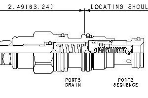
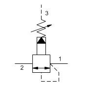
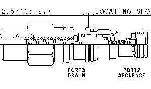
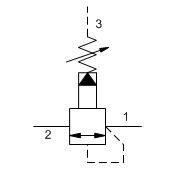
SUN HYDRAULICS Pilot-operated, balanced piston sequence valve (RSBCLBN)
£273.60
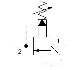
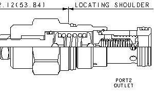
Pilot-operated, balanced piston sequence valves will supply a secondary circuit with flow once the pressure at the inlet (port 1) has exceeded the valve setting. The pressure setting of a sequence valve controls the pressure at port 1 relative to the pressure at the drain (port 3). These valves are insensitive to back pressure at port 2 (sequence), up to the valve setting. They may be used to regulate pressure in place of 2-port relief valves if there is pressure in the return line.
- All 3 port sequence cartridges are physically and functionally interchangeable (i.e. same flow path, same cavity for a given frame size).
- Pilot flow continues to increase as the pressure at port 1 (inlet), relative to the pressure at port 3 (drain), rises above the valve setting.
- The main stage orifice is protected by a 150 micron stainless steel screen.
- Minimum setting is 75 psi (5 bar) for all spring ranges.
- Pressure at port 3 is directly additive to the valve setting at a 1:1 ratio and should not exceed 5000 psi (350 bar).
- Not suitable for use in load holding applications due to spool leakage.
Available on backorder
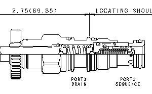
SUN HYDRAULICS Pilot-operated, balanced piston sequence valve (RSBCLQN)1
£288.00
Pilot-operated, balanced piston sequence valves will supply a secondary circuit with flow once the pressure at the inlet (port 1) has exceeded the valve setting. The pressure setting of a sequence valve controls the pressure at port 1 relative to the pressure at the drain (port 3). These valves are insensitive to back pressure at port 2 (sequence), up to the valve setting. They may be used to regulate pressure in place of 2-port relief valves if there is pressure in the return line.
- All 3 port sequence cartridges are physically and functionally interchangeable (i.e. same flow path, same cavity for a given frame size).
- Pilot flow continues to increase as the pressure at port 1 (inlet), relative to the pressure at port 3 (drain), rises above the valve setting.
- The main stage orifice is protected by a 150 micron stainless steel screen.
Available on backorder
SUN HYDRAULICS Pilot-operated, balanced piston sequence valve (RSDCKBN)
£304.80
Pilot-operated, balanced piston sequence valves will supply a secondary circuit with flow once the pressure at the inlet (port 1) has exceeded the valve setting. The pressure setting of a sequence valve controls the pressure at port 1 relative to the pressure at the drain (port 3). These valves are insensitive to back pressure at port 2 (sequence), up to the valve setting. They may be used to regulate pressure in place of 2-port relief valves if there is pressure in the return line.
- All 3 port sequence cartridges are physically and functionally interchangeable (i.e. same flow path, same cavity for a given frame size).
- Pilot flow continues to increase as the pressure at port 1 (inlet), relative to the pressure at port 3 (drain), rises above the valve setting.
- The main stage orifice is protected by a 150 micron stainless steel screen.
Available on backorder
SUN HYDRAULICS Pilot-operated, balanced piston sequence valve (RSDCLBN)
£273.60
Pilot-operated, balanced piston sequence valves will supply a secondary circuit with flow once the pressure at the inlet (port 1) has exceeded the valve setting. The pressure setting of a sequence valve controls the pressure at port 1 relative to the pressure at the drain (port 3). These valves are insensitive to back pressure at port 2 (sequence), up to the valve setting. They may be used to regulate pressure in place of 2-port relief valves if there is pressure in the return line.
- All 3 port sequence cartridges are physically and functionally interchangeable (i.e. same flow path, same cavity for a given frame size).
- Pilot flow continues to increase as the pressure at port 1 (inlet), relative to the pressure at port 3 (drain), rises above the valve setting.
- The main stage orifice is protected by a 150 micron stainless steel screen.
- Pressure at port 3 is directly additive to the valve setting at a 1:1 ratio and should not exceed 5000 psi (350 bar).
- Not suitable for use in load holding applications due to spool leakage.