
Available on backorder
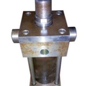
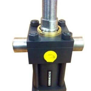
STANDARD HYDRAULIC CYLINDER (BORE DIA 80MM/ ROD DIA 56MM/ STROKE 900MM) TRUNION FRONT FLANGE
£1,422.00
Standard Bore Diameter Sizes – 80 mm
Rod Diameters – 56 mm
Stroke - 900 mm
Max Working Pressure – 160 Bar
Port Size - G 3/4"
Heavy Duty Service – Industrial Tie Rod construction
Standard Hydraulic Cylinder : ISO 6020/2
Mounting - Trunion Front Flange
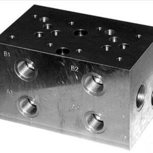
Standard Manifold Block (NG10/Cetop 05) – Double Station
£154.80
A hydraulic manifold is a manifold that regulates fluid flow between pumps and actuators and other components in a hydraulic system. It is like a switchboard in an electrical circuit because it lets the operator control how much fluid flows between which components of a hydraulic machinery.
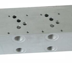
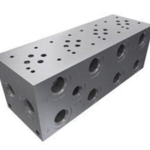
Standard Manifold Block (NG10/Cetop 05) – Four Station
A hydraulic manifold is a manifold that regulates fluid flow between pumps and actuators and other components in a hydraulic system. It is like a switchboard in an electrical circuit because it lets the operator control how much fluid flows between which components of a hydraulic machinery.
Get Quote
[contact-form-7 404 "Not Found"]
Standard Manifold Block (NG10/Cetop 05) – Single Station
£90.00
A hydraulic manifold is a manifold that regulates fluid flow between pumps and actuators and other components in a hydraulic system. It is like a switchboard in an electrical circuit because it lets the operator control how much fluid flows between which components of a hydraulic machinery.
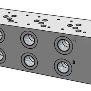
Standard Manifold Block (NG10/Cetop 05) – Three Station
£252.00
A hydraulic manifold is a manifold that regulates fluid flow between pumps and actuators and other components in a hydraulic system. It is like a switchboard in an electrical circuit because it lets the operator control how much fluid flows between which components of a hydraulic machinery.
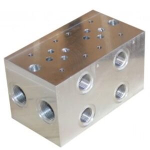
Standard Manifold Block (NG6/Cetop 03) – Double Station
£79.20
A hydraulic manifold is a manifold that regulates fluid flow between pumps and actuators and other components in a hydraulic system. It is like a switchboard in an electrical circuit because it lets the operator control how much fluid flows between which components of a hydraulic machinery.

Standard Manifold Block (NG6/Cetop 03) – Five Station
A hydraulic manifold is a manifold that regulates fluid flow between pumps and actuators and other components in a hydraulic system. It is like a switchboard in an electrical circuit because it lets the operator control how much fluid flows between which components of a hydraulic machinery.
Get Quote
[contact-form-7 404 "Not Found"]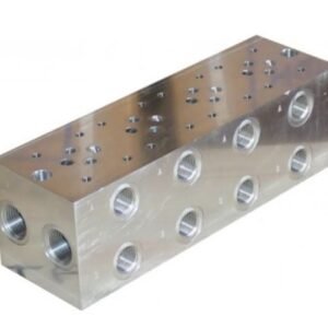
Standard Manifold Block (NG6/Cetop 03) – Four Station
A hydraulic manifold is a manifold that regulates fluid flow between pumps and actuators and other components in a hydraulic system. It is like a switchboard in an electrical circuit because it lets the operator control how much fluid flows between which components of a hydraulic machinery.
Get Quote
[contact-form-7 404 "Not Found"]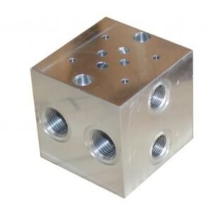
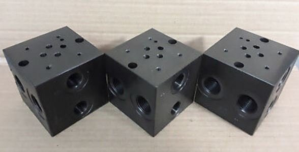
Standard Manifold Block (NG6/Cetop 03) – Single Station
£43.20
A hydraulic manifold is a manifold that regulates fluid flow between pumps and actuators and other components in a hydraulic system. It is like a switchboard in an electrical circuit because it lets the operator control how much fluid flows between which components of a hydraulic machinery.
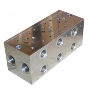
Standard Manifold Block (NG6/Cetop 03) – Three Station
£129.60
A hydraulic manifold is a manifold that regulates fluid flow between pumps and actuators and other components in a hydraulic system. It is like a switchboard in an electrical circuit because it lets the operator control how much fluid flows between which components of a hydraulic machinery.
Available on backorder

SUN HYDRAULICS 10:1 pilot ratio, standard capacity counterbalance valve (CBCHLKN)
£396.00
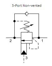
Counterbalance valves with pilot assist are meant to control an overrunning load. The check valve allows free flow from the directional valve (port 2) to the load (port 1) while a direct-acting, pilot-assisted relief valve controls flow from port 1 to port 2. Pilot assist at port 3 lowers the effective setting of the relief valve at a rate determined by the pilot ratio.
Other names for this valve include motion control valve and over-center valve.
- Counterbalance valves should be set at least 1.3 times the maximum load induced pressure.
- Turn adjustment clockwise to decrease setting and release load.
- Full clockwise setting is less than 200 psi (14 bar).
- Backpressure at port 2 adds to the effective relief setting at a ratio of 1 plus the pilot ratio times the backpressure.
Available on backorder


SUN HYDRAULICS 10:1 pilot ratio, standard capacity counterbalance valve(CBGHLJN)
£1,152.00
Counterbalance valves with pilot assist are meant to control an overrunning load. The check valve allows free flow from the directional valve (port 2) to the load (port 1) while a direct-acting, pilot-assisted relief valve controls flow from port 1 to port 2. Pilot assist at port 3 lowers the effective setting of the relief valve at a rate determined by the pilot ratio.
Other names for this valve include motion control valve and over-center valve.
- Counterbalance valves should be set at least 1.3 times the maximum load induced pressure.
- Turn adjustment clockwise to decrease setting and release load.
- Full clockwise setting is less than 200 psi (14 bar).
- Backpressure at port 2 adds to the effective relief setting at a ratio of 1 plus the pilot ratio times the backpressure.